
Embedded Systems and Power Electronics

Total Pageviews

About Me

My photo
I am currently a PhD student at UC Berkeley, following a 6-year journey working at Apple after my undergrad years at Cornell University. I am a 2025 Paul & Daisy Soros fellow. I grew up in Dhaka, Bangladesh where my interest in electronics was cultivated, resulting in the creation of this blog.

BTemplates.com

Powered by Blogger.

Showing posts with label transformer. Show all posts

Dec 31, 2024

Insights from repairing a 30V 5A power supply (BPS-305)


When I started working on a project (hopefully more on that soon), I reached out for an old 30V 5A power supply (Lavolta BPS-305). I rotated the voltage dial to try to get to 24V and observed that the voltage would not go past 15V, even though it is rated for 30V. Even though this supply was a few years old, I had not personally used it before. So, it wasn't clear whether it was a previously-functioning supply that stopped working, or whether it was always broken.

Fig. 1 - Lavolta BPS-305 power supply

Upon some more poking and prodding, I identified that the power supply had several issues:

  1. Output voltage only goes up to about 15V instead of 30V max.
  2. Output voltage is not stable and fluctuates at steady state, appearing unregulated. See video below.
  3. Output voltage flickers when relays switch around ~7V and ~14V and the relays keep flickering unless the voltage is moved far away from the transition points.
  4. Output current measurement (when HI/LO button is pressed down to LO) is off by a factor of 2.
  5. Output current measurement (when HI/LO button is pressed up to HI) displays zero.
Output voltage unstable at "steady state" - moving between 10.2V to 11.1V with a fixed output load

Hopeful that I can repair the supply, I opened it up. Noticing a relatively simple one-layer PCB, I set out to find a schematic or other reference for the supply. This is where I realized that many many (low-cost) 30V 5A power supplies are based on the same couple designs. I'll link to a few useful resources here that I came across during my search:

Instead of going through all my investigations, I'll highlight a few standouts here.

Broken potentiometers

After lots of investigating, the key offenders were 2 broken potentiometers. Referring to the file PS305D Schematic Main in the Drive link, these are VR104 and VR102. These are shown below in Fig. 2.
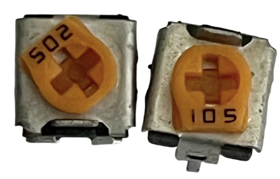
Fig. 2 - The culprits. VR104 is marked 502 (5kΩ) and VR102 is marked 501 (500Ω). Both parts measure open at component ends.

VR104 is used for output voltage feedback. Once this part was replaced with a functioning 5kΩ pot, the output voltage was now stable and would go all the way up to 30V. The pot is trimmed until the max output voltage is 30V.

VR102 sets the max output current when the HI/LO button is released (HI -> 5A current limit). There was no current limit being set in this setting with the faulty part. Since I did not have a 500Ω pot on hand, I replaced VR102 with a 5kΩ pot in parallel with a 470Ω resistor. This allows tuning the resistance as shown in Fig. 3. Fig. 4 shows the parallel 470Ω resistor soldered on the back side of the board. Once these parts were provisioned, the 5kΩ pot was trimmed until the max output current was set to 5A. The red dot in Fig. 3 indicates the final trimmed resistance.

Fig. 3 - combined resistance of 5kΩ pot in parallel with 470Ω resistance as the pot is trimmed.

Fig. 4 - soldered 470Ω resistor in parallel with VR102

FIg. 5 - the two blue potentiometers replace the broken ones in Fig. 2

Tuning the current display

Fig. 6 - Output current reading 6.89A when the real measured value is 5A
Fig. 7 - DMM on the PSU; the trim pots are the blue components near each chip. Left display is for current and the corresponding trimpot is VR211. Right display is for voltage and the corresponding trimpot is VR201.

When the HI/LO button is pushed down to the LO position, the PSU's output current limit is set to 2.5A tuned by VR101. When the HI/LO button is at the HI position, the output limit is set by VR102 (and the parallel 470Ω resistor) as described previously. However, there was a fair bit of error on this reading, as shown in Fig. 6. By adjusting VR305 (see PS305D Schematic Controls in the Drive link) in conjunction with the reference voltage set by the blue trimpot VR211 (see PS305D Schematic Display in the Drive link) in Fig. 7, the output current can be tuned. Since VR211 affects the reference voltage for the current meter, adjusting it affects both the HI and LO current readings. The procedure then was to set the switch to HI and then tune VR211; once that is corrected, switch to LO and then tune VR305.

Relay-selectable transformer secondary winding

Fig. 8 - secondary selection scheme with relay

Because the regulation stage in the power supply is based on a linear regulator, the difference between the input and output power is dissipated as heat. Since the power supply has a large selectable output range, this would result in very high power dissipation in the regulator at lower input voltages. To overcome this drawback and reduce the power dissipation, the power supply utilizes a selector circuit on the secondary as shown in Fig. 8.

As an example, let's consider that the output power is desired to be 3.3V. Suppose the input voltage post-rectifier is 40V (which is the case between S3-S0 for the BPS-305). At an output current of 3A, the power dissipated in the regulator would be roughly: Pout-Pin = Vout*Iout - Vin*Iin ~ (Vout-Vin)*Iout = 110.1W.  All this for only 13.2W of output power. At lower output voltages and higher output currents, this gets even worse!

By using the scheme shown in Fig. 8, the voltage at the input of the regulator is selected based on the desired output voltage to reduce power dissipation. With the example above, now suppose that for 3.3V, the input to the regulator is 14.8V, the power dissipation is reduced to 34.5W now! That's 75W less than the previous example!

For my unit, the voltage bins transitions happen for output voltages 8V, 15V, 21V and 30V. This is a good design decision rather than having a fixed 40V input for the regulator.

Output testing

For testing the output, different resistor combinations were used as the load. In addition, a constant current circuit was used even as the output voltage is varied. A simple circuit can be designed using the jellybean LM317 part. The datasheet shows an example circuit in Section 9.3.3 (Precision Current-Limiter Circuit).
Fig. 9 - constant current circuit using LM317

The output (ADJUST pin) is tied to GND for testing. Using R1 = 4.7Ω provides a ~250mA constant current load. Similarly, R1 is swapped out for lower values for higher currents. It is important to have a heatsink mounted on the LM317, especially at higher voltages. This constant current value was also used to validate the output current display across PSU output voltages.

Other observations

  1. The logic GND for the electronics are shorted to the positive output instead of the negative output. Even though the circuits in the PSU closely reflect those of PS305D Schematic Main/Display/Controls, this grounding scheme is reflected in hy_3005_dc_power_supply.
  2. Many of these 30V 5A power supplies seem to be based on a couple base designs with slight tweaks in implementation.
  3. The build quality appears shoddy. Many components were haphazardly soldered - many caps weren't fully seated. The fan wires run adjacent to (and touch) the (potentially very hot) heatsink for the transistors. However, none of these appear to impact functionality, at least in the short term.

Feb 16, 2014

Automatic voltage stabilizer (AC-AC) with PIC16F873A - circuit, explanation, PCB, source code, videos and loads of pictures!


Download links for the article: 

Google docs (go to the link, click File in the PDF window, then click Download):
https://docs.google.com/file/d/0B4SoPFPRNziHb3VrX3JhWko3d1E/edit

Scribd link: http://www.scribd.com/doc/207498741/Automatic-Voltage-Stabilizer-with-PIC16F873A

4shared download link: http://www.4shared.com/office/ktU0k9dqba/Voltage_Stabilizer.html


You can download all the files related to the voltage stabilizer:

Google docs (go to the link, click File in the PDF window, then click Download):

PCB images:


Dec 23, 2012

Ferrite Transformer Turns Calculation for High-Frequency/SMPS Inverter


On different forums, I often find people asking for help in calculating the required turns for a ferrite transformer they are going to use in high-frequency/SMPS inverters. In a high-frequency/SMPS inverter, the ferrite transformer is used in the step-up/boost stage where the low voltage DC from the battery is stepped up to high voltage DC. In this situation, there are really only two choices when selecting topology – push-pull and full-bridge. For transformer design, the difference between a push-pull and a full-bridge transformer for same voltage and power will be that the push-pull transformer will require a center tap, meaning it will require twice the number of primary turns as the full-bridge transformer.

Calculation of required turns is actually quite simple and I’ll explain this here.

For explanation, I’ll use an example and go through the calculation process.

Let’s say the ferrite transformer will be used in a 250W inverter. The selected topology is push-pull. The power source is a 12V battery. Output voltage of the DC-DC converter stage will be 310V. Switching frequency is 50kHz. The selected core is ETD39. Remember that the output of the transformer will be high frequency AC (50kHz square wave in this case). When I refer to an output of high voltage DC (eg 310VDC mentioned above), this is the DC output obtained after rectification (using ultrafast recovery diodes configured as bridge rectifier) and filtration (using LC filter).

During operation, the battery voltage does not stay fixed at 12V. With high loads, the voltage will be less than 12V. With low loads and near-fully charged battery, the voltage may be higher than 13V. So, it must be kept in mind that the input voltage is not constant, but is variable. In inverters, the battery low-cut is usually set at 10.5V. So, we’ll take this as our lowest possible input voltage.

Vinmin = 10.5V

The formula for calculating the number of required primary turns is:

 
For our push-pull transformer, this will be one-half the required number of turns.
Npri means number of primary turns; Nsec means number of secondary turns; Naux means number of auxiliary turns and so on. But just N (with no subscript) refers to turns ratio.

For calculating the required number of primary turns using the formula, the parameters or variables that need to be considered are:

  • Vin(nom) – Nominal Input Voltage. We’ll take this as 12V. So, Vin(nom) = 12.
  • f – The operating switching frequency in Hertz. Since our switching frequency is 50kHz, f = 50000.
  • Bmax – Maximum flux density in Gauss. If you’re used to using Tesla or milliTesla (T or mT) for flux density, just remember that 1T = 104 Gauss. Bmax really depends on the design and the transformer cores being used. In my designs, I usually take Bmax to be in the range 1300G to 2000G. This will be acceptable for most transformer cores. In this example, let’s start with 1500G. So Bmax = 1500. Remember that too high a Bmax will cause the transformer to saturate. Too low a Bmax will be under utilizing the core.
  • Ac – Effective Cross-Sectional Area in cm2. You will get this information from the datasheets of the ferrite cores. Ac is also sometimes referred to as Ae. For ETD39, the effective cross-sectional area given in the datasheet/specification sheet (I’m referring to TDK E141. You can download it from here: www.tdk.co.jp/tefe02/e141.pdf  ), the effective cross-sectional area (in the specification sheet, it’s referred to as Ae but as I’ve said, it’s the same thing as Ac) is given as 125mm2. That is equal to 1.25cm2. So, Ac = 1.25 for ETD39.
 
So now, we’ve obtained the values of all required parameters for calculation Npri – the number of required primary turns.

Vin(nom) = 12                                        f = 50000                              Bmax = 1500                          Ac = 1.25

Plugging these values into the formula:


                        Npri = 3.2


We won’t be using fractional windings, so we’ll round off Npri to the nearest whole number, in this case, rounded down to 3 turns. Now, before we finalize this and select Npri = 3, we better make sure that Bmax is still within acceptable bounds. As we’ve decreased the number of turns from the calculated figure (down to 3.0 from 3.2), Bmax will increase. We now need to figure out just how much Bmax has increased and if that is still an acceptable value.

Vin(nom) = 12                 f = 50000                     Npri = 3                         Ac = 1.25


                                                                   Bmax = 1600


The new value of Bmax is well within acceptable bounds and so we can proceed with Npri = 3.

So, we now know that for the primary, our transformer will require 3 turns + 3 turns.

In any design, if you need to adjust the values, you can easily do so. But always remember to check that Bmax is acceptable.

  • For example, if for construction difficulties, winding 3 turns + 3 turns becomes difficult, you may use 2 turns + 2 turns or 4 turns + 4 turns. Increasing number of turns won’t hurt – you’ll just be under utilizing the core. However, decreasing number of turns increases Bmax, so just recheck to make sure Bmax is okay. The range I’ve stated for Bmax (1300G to 2000G) is just an estimate. It will work for most cores. However, with many cores, you can go higher to decrease the number of turns. Going lower will just be under utilizing the core, but may sometimes be required if number of turns is too low. 
 
  • I’ve started off with a set Bmax and gone on to calculate Npri from there. You can also assign a value of Npri and then check if Bmax is okay. If not, you can then increase or decrease Npri as required and then check if Bmax is okay, and repeat this process until you get a satisfactory result. For example, you may have set Npri = 2 and calculated Bmax and decided that this was too high. So, you set Npri = 3 and calculated Bmax and decided it was okay. Or you may have started with Npri = 4 and calculated Bmax and decided that it was too low. So, you set Npri = 3 and calculated Bmax and decided it was okay.


Now it’s time to move on to the secondary. The output of our DC-DC converter is 310V. So, the transformer output must be 310V at all input voltages, from all the way up from 13.5V to all the way down to 10.5V. Naturally, feedback will be implemented to keep the output voltage fixed even with line and load variations – changes due to battery voltage change and also due to load change. So, some headroom must be left for feedback to work. So, we’ll design the transformer with secondary rated at 330V. Feedback will just adjust the voltage required by changing the duty cycle of the PWM control signals. Besides feedback, the headroom also compensates for some of the losses in the converter and thus compensates for the voltage drops at different stages – for example, in the MOSFETs, in the transformer itself, in the output rectifiers, output inductor, etc.

This means that the output must be capable of supplying 330V with input voltage equal to 10.5V and also input voltage equal to 13.5V. For the PWM controller, we’ll take maximum duty cycle to be 98%. The gap allows for dead-time.

At minimum input voltage (when Vin = Vinmin), duty cycle will be maximum. Thus duty cycle will be 98% when Vin = 10.5 = Vinmin. At maximum duty cycle = 98%, voltage to transformer = 0.98 * 10.5V = 10.29V.

So, voltage ratio (secondary : primary) = 330V : 10.29V = 32.1

Since voltage ratio (secondary : primary) = 32.1, turns ratio (secondary : primary) must also be 32.1 as turns ratio (secondary : primary) = voltage ratio (secondary : primary). Turns ratio is designated by N. So, in our case, N = 32.1 (I’ve taken N as the ratio secondary : primary).

Npri = 3

Nsec = N * Npri = 32.1 * 3 = 96.3

Round off to the nearest whole number. Nsec = 96.

Thus 96 turns are required for the secondary. With proper implementation of feedback, a constant 310VDC output will be obtained throughout the entire input voltage range of 10.5V to 13.5V.

Here, one thing to note is that even though I took 98% as the maximum duty cycle, maximum duty cycle in practice will be smaller since our transformer was calculated to provide 330V output. In the circuit, the output will be 310V, so the duty cycle will be even lower. However, the advantage here is that you can be certain that the output will not drop below 330V even with heavy loads since a large enough headroom is provided for feedback to kick in and maintain the output voltage even at high loads.

If any auxiliary windings are required, the required turns can be easily calculated. Let me show with an example. Let’s say we need an auxiliary winding to provide 19V. I know that the output 310V will be regulated, whatever the input voltage may be, within the range initially specified (Vinmin to Vinmax – 10.5V to 13.5V). So, the turns ratio for the auxiliary winding can be calculated with respect to the secondary winding. Let’s call this turns ratio (secondary : auxiliary) NA.

NA = Nsec / Naux = Vsec / (Vaux + Vd). Vd is the output diode forward drop. Let’s assume that in our application, a schottky rectifier with a Vd = 0.5V is used.

So, NA = 310V / 19.5V =15.9

Nsec / Naux = NA

Naux = Nsec / NA = 96 / 15.9 = 5.96

Let’s round off Naux to 6 and see what the output voltage is.

Vsec / (Vaux + Vd) = NA = Nsec / Naux = 96 / 6 =16.0

(Vaux + Vd) = Vsec / NA = 310V / 16.0 = 19.375V

Vaux = 19.375V – 0.5V = 18.875V (rounded off)

I would say that’s great for an auxiliary supply. If in your calculations you come to a voltage that is too far off the required target voltage and thus greater accuracy is required, take Vaux as something higher and use a voltage regulator.

For example, if in our previous example, instead of18.875V we had gotten 19.8V but needed more accuracy, we could've used 24V or thereabouts and used a voltage regulator to give 19V output.

So, there we have it. Our transformer has 3 turns + 3 turns for primary, 96 turns for secondary and 6 turns for auxiliary.

Here’s our transformer:

Calculating required number of turns for a transformer is actually a simple task and I hope that I could help you understand how to do this. I hope this tutorial helps you in your ferrite transformer designs. Do let me know your comments and feedback.