
Using the SG3525 PWM Controller - Explanation and Example: Circuit Diagram / Schematic of Push-Pull Converter
PWM is used in all sorts of power control and converter
circuits. Some common examples include motor control, DC-DC converters, DC-AC
inverters and lamp dimmers. There are numerous PWM controllers available that
make the use and application of PWM quite easy. One of the most popular of such
controllers is the versatile and ubiquitous SG3525 produced by multiple manufacturers – ST
Microelectronics, Fairchild Semiconductors, On
Semiconductors, to name a few.
SG3525 is used extensively in DC-DC converters, DC-AC
inverters, home UPS systems, solar inverters, power supplies, battery chargers
and numerous other applications. With proper understanding, you can soon start
using SG3525 yourself in such applications or any other application really that
demands PWM control.
Before going on to the description and application, let’s first
take a look at the block diagram and the pin layout.
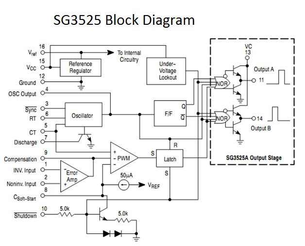

Pins 1 (Inverting Input) and 2 (Non Inverting Input) are the
inputs to the on-board error amplifier. If you are wondering what that is, you
can think of it as a comparator that controls the increase or decrease of the
duty cycle for the “feedback” that you associate with Pulse Width Modulation
(PWM).
This functions either to increase or decrease the duty cycle
depending on the voltage levels on the Inverting and Non-Inverting Inputs –
pins 1 and 2 respectively.
- When voltage on the Inverting Input (pin 1) is greater than voltage on the Non-Inverting Input (pin 2), duty cycle is decreased.
- When voltage on the Non-Inverting Input (pin 2) is greater than voltage on the Inverting Input (pin 1), duty cycle is increased.
The frequency of PWM is dependent on the timing capacitance
and the timing resistance. The timing capacitor (CT) is connected between pin 5
and ground. The timing resistor (RT) is connected between pin 6 and ground. The
resistance between pins 5 and 7 (RD) determines the deadtime (and also slightly
affects the frequency).
The frequency is
related to RT, CT and RD by the relationship:

With RT and RD in Ω and CT in F, f is in Hz.
Typical values of RD are in the range 10Ω to 47Ω.
The range of values usable (as specified by the manufacturers of SG3525) is 0Ω
to 500Ω.
RT must be within the range 2kΩ to 150kΩ. CT must be within the
range 1nF (code 102) to 0.2µF (code 224). The oscillator frequency must be
within the range 100Hz to 400kHz. There is a flip-flop before the driver stage,
due to which your output signals will have frequencies half that of the
oscillator frequency that is calculated using the above mentioned formula. So,
if you are looking to use this for a 50Hz inverter, you require drive signals
of 50Hz. So, the oscillator frequency must be 100Hz.
A capacitance connected between pin 8 and ground provides
the soft-start functionality. The larger the capacitance, the larger the
soft-start time. This means that the time taken to go from 0% duty cycle to the
desired duty cycle or maximum duty cycle is larger. So, the duty cycle
increases more slowly initially. Keep in mind that this only affects initial
rate of increase of duty cycle, ie, the rate of increase of duty cycle after
the SG3525 starts up.
Typical values of the soft-start capacitance lie within the
range 1µF
to 22µF
depending on the desired soft-start time.
Pin 16 is the output from the voltage reference section.
SG3525 contains an internal voltage reference module rated at +5.1V that is
trimmed to provide a ±1% accuracy. This reference is often used to provide a
reference voltage to the error amplifier for setting the feedback reference
voltage. It can be directly connected to one of the inputs or a voltage divider
can be used to further scale down the voltage.
Pin 15 is VCC – the supply voltage to the SG3525 that makes
it run. VCC must lie within the range 8V to 35V. SG3525 has an under-voltage
lockout circuit that prevents operation when VCC is below 8V, thus preventing
erroneous operation or malfunction.
Pin 13 is VC – the supply voltage to the SG3525 driver
stage. It is connected to the collectors of the NPN transistors in the output
totem-pole stage. Hence the name VC. VC must lie within the range 4.5V to 35V.
The output drive voltage will be one transistor voltage drop below VC. So when
driving Power MOSFETs, VC should be within the range 9V to 18V (as most Power
MOSFETs require minimum 8V to be fully on and have a maximum VGS breakdown
voltage of 20V). For driving logic level MOSFETs, lower VC may be used. Care
must be taken to ensure that the maximum VGS breakdown voltage of the MOSFET is
not crossed. Similarly when the SG3525 outputs are fed to another driver or
IGBT, VC must be selected accordingly, keeping in mind the required voltage for
the device being fed or driven. It is common practice to tie VC to VCC when VCC
is below 20V.
Pin 12 is the Ground connection and should be connected to
the circuit ground. It must share a common ground with the device it drives.
Pins 11 and 14 are the outputs from which the drive signals
are to be taken. They are the outputs of the SG3525 internal driver stage and can
be used to directly drive MOSFETs and IGBTs. They have a continuous current
rating of 100mA and a peak rating of 500mA. When greater current or better
drive is required, a further driver stage using discrete transistors or a
dedicated driver stage should be used. Similarly a driver stage should be used
when driving the device causing excessive power dissipation and heating of
SG3525. When driving MOSFETs in a bridge configuration, high-low side drivers
or gate-drive transformers must be used as the SG3525 is designed only for
low-side drive.
Pin 10 is shutdown. When this pin is low, PWM is enabled.
When this pin is high, the PWM latch is immediately set. This provides the
fastest turn-off signal to the outputs. At the same time the soft-start
capacitor is discharged with a 150µA current source. An alternative
method of shutting down the SG3525 is to pull either pin 8 or pin 9 low.
However, this is not as quick as using the shutdown pin. So, when quick
shutdown is required, a high signal must be applied to pin 10. This pin should
not be left floating as it could pick up noise and cause problems. So, this pin
is usually held low with a pull-down resistor.
Pin 9 is compensation. It may be used in conjunction with
pin 1 to provide feedback compensation.
Now that we’ve seen the function of each pin, let’s design a
circuit with the SG3525 and see how it is put to use practically.
Let’s make a circuit running at 50kHz, driving MOSFETs (in a push-pull configuration) that
drive a ferrite core which then steps up the high frequency AC and then is
rectified and filtered to give a 290V regulated output DC that can be used to
run one or more CFLs.
For the turns calculation, check out my article "Ferrite Transformer Turns Calculation for High-Frequency/SMPS Inverter": http://tahmidmc.blogspot.com/2012/12/ferrite-transformer-turns-calculation.html
So here’s the circuit (click on the circuit to enlarge the image):

Let’s analyze it and see what I’ve done.
You can firstly see that the supply voltage has been
provided and ground has been connected. Also notice that VC has been connected
to VCC. I’ve added a bulk and a decoupling capacitor across the supply pins.
The decoupling capacitor (0.1µF) should be placed as close to the
SG3525 as possible. You should always use this in all your designs. Do not omit
the bulk capacitor either, although you may use a smaller value.
Let’s see pins 5, 6 and 7. I’ve added a small resistance RD
(between pins 5 and 7) that provides a little deadtime. I’ve connected RT
between pin 6 and ground and CT between pin 5 and ground. RD = 22Ω,
CT = 1nF (Code: 102) and RT = 15kΩ. This gives an oscillator frequency
of:

As the oscillator frequency is 94.6kHz,
the switching frequency is 0.5 * 94.6kHz = 47.3kHz and this is close enough to
our target frequency of 50kHz. Now if you had needed 50kHz accurate, then the
best way would have been to use a pot (variable resistor) in series with RT and
adjust the pot, or to use a pot (variable resistor) as RT, although I prefer
the first as it allows for fine tuning the frequency.
Let’s look at pin 8 now. I’ve connected a
1µF
capacitor from pin 8 to ground and this provides a small soft-start. I’ve
avoided using too large a soft-start as the slow duty cycle increase (and thus
the slow increase in voltage) causes problems when using CFLs at the output.
Let’s look at pin 10 now. Initially it’s
pulled up to VREF with a pull-up resistor. So, PWM is disabled and does not
run. However, when the switch is on, pin 10 is now at ground and so PWM is
enabled. So, we’ve made use of the SG3525 shutdown option (via pin 10). Thus
the switch acts like an on/off switch.
Pin 2 is connected to VREF and is thus at
a potential of +5.1V (±1%). The output of the converter is connected to pin 1 through a
voltage divider with resistances 56kΩ and 1kΩ. Voltage ratio is 57:1. At feedback “equilibrium”, voltage at pin
1 is 5.1V as well as this is the target of the error amplifier – to adjust the
duty cycle to adjust the voltage at pin 1 so that it is equal to that of pin 2.
So, when voltage at pin 1 is 5.1V, voltage at output is 5.1V * 57 = 290.7V and
this is close enough to our 290V target. If greater accuracy is required, one
of the resistors can be either replaced with a pot or in series with a pot and
the pot adjusted to give required reading.
The parallel combination of the resistor and capacitor between
pins 1 and 9 provides feedback compensation. I won’t go into detail into feedback
compensation as it is a vast topic on its own.
Pins 11 and 14 drive the MOSFETs. There are resistors in series
with the gate to limit gate current. The resistors from gate-to-source ensure
that MOSFETs don’t get accidentally turned on.
So that’s about it. You can see that this is quite an easy circuit
to design. If you’ve understood all of this, you can now design circuits with
SG3525 yourself. Try to make a few, eg for 50Hz output and with isolated
feedback. If you can’t don’t worry, I’ll put up another article with a few more
circuits using SG3525 so that you become completely clear with it (if you haven’t
already).
-----------------------------------------------------------------------------------------------------
Reference documents:
SG3525 datasheet: www.onsemi.com/pub/Collateral/SG3525A-D.PDF
Ferrite Transformer Turns Calculation for High-Frequency/SMPS Inverter: http://tahmidmc.blogspot.com/2012/12/ferrite-transformer-turns-calculation.html


A tip you got some good information here but, the colour scheme you choose are not good for readability, its really bad.. Try white on black instead if the inverse (as you have it currently).
ReplyDeleteI'll keep that in mind and will make changes if necessary. Thanks for the input.
DeleteRegards,
Tahmid.
hello tahmid I have a question here. I am building a high frequency inverter. I use irfz46 in the dc to dc section and the dc voltage stands up good under a load of 300 watt when I use irf3205 in stead which can handle more current the dc voltage falls off to 35v from 165v . Could this be defective 3205 fets or I need to change components to match the irf3205. Thanks for ur support
DeleteIt could be defective IRF3205's. But before that, you should make sure that the MOSFETs are properly driven. If they aren't properly driven to turn them fully on, the problem could lie there. So, add a driver circuit (totem-pole or discrete driver based, eg TC427) and then test again.
DeleteSee here: http://tahmidmc.blogspot.com/2012/12/low-side-mosfet-drive-circuits-and_23.html
Regards,
Tahmid.
Oh thank you Tahmid i will try this driver and let you know the results.keep the good work going
DeleteHi Tahmid,
ReplyDeleteWhat is the role of R3 in the above circuit?
Regards,
Prasanth.
Hi Prasanth,
ReplyDeleteR3 pulls up pin 2 to the level of VREF and is thus used as reference voltage (at pin 2) for the error amplifier.
Regards,
Tahmid.
Hi Tahmid,
ReplyDeleteI am sorry if u misunderstood my question. I mean if the value of R3 is made 0 ohms, is it going to make any difference? If I am right, the input of the comparators are having very high impedance.
Regards,
Prasanth.
Yeah, it shouldn't be a problem. If you won't use pin 2 with any voltage divider circuit and just need to provide 5V, you should just be able to connect it to VREF. The inputs to the error amplifier should have high impedance.
DeleteRegards,
Tahmid.
hi,
ReplyDeletetahmid i really need your help i already mailed you some info may be you didnt chek it kindly reply me i m in trouble.
Regards:
Waqas.(mah****le@hotmail.com)
Check your inbox.
DeleteI'll answer your question here as well:
The PIC, in a sine wave inverter, is used to generate the SPWM signals and do the "housekeeping" tasks as well - battery low cut, overload, battery high cut and other protection, etc. And you also have the benefit of not being able to copy someone else's work!
Regards,
Tahmid.
thanks tahmid for your tutorials.
ReplyDeleteplease can you guide me on how to use TL431 and optocoupler as feeback for sg3525.
thanks..
Hi abm,
DeleteI'm glad that the tutorials were of help.
I'll try to write up an article on TL431 and optocoupler for feedback for SG3525.
Regards,
Tahmid.
thanks tahmid i will be looking forward to that.
Deleteyou just made these SG3525 a plaything for me i am enjoying it. i have placed order fro ferrite inductors hope to start learning smps, atleast enough of simulation.
thanks for all your effort may God grant you more ease of wisdom and knowledge (amen).
hi tahmid """"
ReplyDeletemy name is mohamed mustafa from egypt please help me to design my power inverter >>> i bought ferrite core ETD34 and i find that at 100 khz this transformer give 321 watt " from data sheet " can i operate irfz44n at 100 khz or this not advisable and i calculate but with 75 khz the number of turns of primary and secondary and i found it :::: Np= 3 turns and Ns= 96 turns >>>> what is the thickness of this wire of both primary and secondary
my email :: ENG_MOHAMEDMUSTAFA@YAHOO.COM
Hi,
Delete321W mentioned in the datasheet is the absolute maximum. You should use it at a considerably lower power level.
The thickness of the wire of the primary and secondary will depend on your selected power level. Remember that you can't use too thick wires due to skin effect, especially since you're operating at 100kHz. Don't use wires thicker than 26 SWG. Then, use multiple 26 SWG wires to handle the required current.
Regards,
Tahmid.
for input 12v 21A 75KHZ 250 watt ...
Deletefor output 310V 0.9A 75KHZ 250 watt...
i wound the primary with wire thick = 22SWG
and the secondary with wire thick = 27SWG
Is that satisfied ?
thank you for helping me
Is there any way to make duty cycle control on SG IC to be from 1 to 99%?....I built few circuits and i tryed many things but i can reach this range on 300Khz.
ReplyDeleteAre you attempting to control the duty cycle without a feedback loop?
Deletehi tahmid ::
ReplyDeletemy design: for my ferrite ETD34transformer
for input 12v 21A 75KHZ 250 watt ...
for output 310V 0.9A 75KHZ 250 watt...
i wound the primary with wire thick = 22SWG
and the secondary with wire thick = 27SWG
Is that satisfied ?
thank you for helping me
Before I go on to check for current rating, I will let you know that SWG 22 wire is too thick for use at 75kHz. Skin effect will play a large part and at high load, the wire will overheat. Use quite a few SWG 26 in parallel to make up the wire with required current handling capacity.
DeleteRegards,
Tahmid.
hi tahmid :
ReplyDeletei purchase the component of above design but i have a question .... in the LC filter of the output the capacitor is 10 micro ..1- what is the withstand voltage of the capacitor ?????
2-what is the specification of this capacitor ?
3-have you pcb lay out of this design?
thank you very much ..........
1) Make sure the voltage is higher than the maximum output voltage. A 400V capacitor would be good since I assume your output voltage would be lower than 330V. If it's higher than that and close to 400V, use 630V.
Delete2) It is an electrolytic capacitor. Try to use a low-ESR capacitor.
3) Unfortunately, I don't have the PCB design for this. There are many free PCB design software you can use to design the PCB yourself.
ExpressPCB: http://www.expresspcb.com/expresspcbhtm/download.htm
Cadsoft EAGLE (freeware with limitation): http://www.cadsoftusa.com/download-eagle/freeware/
PCB123: http://www.sunstone.com/pcb123.aspx
DesignSpark PCB: http://www.designspark.com/page/designspark-pcb-home-page
DipTrace (freeware with limitation): http://www.diptrace.com/
TINA: http://www.tina.com/English/tina/
gEDA: http://www.gpleda.org/
KiCad EDA: http://www.kicad-pcb.org/display/KICAD/KiCad+EDA+Software+Suite
There are other free PCB design software available as well.
So, download one. Go through the manual and start using it.
I've used ExpressPCB and PCB123 (a little bit of EAGLE as well). I'd say they're pretty good and certainly good enough for your purpose.
Hope this helps!
Regards,
Tahmid.
Hi,
ReplyDeleteit's really an interesting topic "Using the SG3525 PWM Controller - Explanation and Example: Circuit Diagram / Schematic of Push-Pull Converter ".As far as my consolation it is an excellent explanation.Thank you dear.
Inverter charger
You're welcome!
DeleteI'm glad you found it helpful.
Regards,
Tahmid.
hello tahmid keep up the good work. I have a question i see ur calculations for transformer.if I calculate the primary turns for a 12 dc supply to 330v say I want to step up my system to 24dc can i use the same primary turns and adjust the secondary for the 330v or my primary turns would also have to be different for 24v.. Thank u for ur support
ReplyDeleteYou should recalculate for 24VDC. Keeping the same primary turns means that you'll have twice the flux density you'll do for 12VDC.
DeleteRegards,
Tahmid.
hi tahmid ",,,,,
ReplyDeleteplz .. i want PCB of this design
I haven't designed PCB for this. There are many free PCB design software you can use to design the PCB yourself.
DeleteExpressPCB: http://www.expresspcb.com/expresspcbhtm/download.htm
Cadsoft EAGLE (freeware with limitation): http://www.cadsoftusa.com/download-eagle/freeware/
PCB123: http://www.sunstone.com/pcb123.aspx
DesignSpark PCB: http://www.designspark.com/page/designspark-pcb-home-page
DipTrace (freeware with limitation): http://www.diptrace.com/
TINA: http://www.tina.com/English/tina/
gEDA: http://www.gpleda.org/
KiCad EDA: http://www.kicad-pcb.org/display/KICAD/KiCad+EDA+Software+Suite
There are other free PCB design software available as well.
So, download one. Go through the manual and start using it.
I've used ExpressPCB and PCB123 (a little bit of EAGLE as well). I'd say they're pretty good and certainly good enough for your purpose.
Regards,
Tahmid.
hi tahmid you are doing some excellent work i see your calculations for the number of primary turns for transformer from 12VDC to 330V could you please calculate from 24VDC TO 330V the number of primary turns because i dont fully understand the steps after setting out the equasion thanks in advance
ReplyDeleteYou should try it yourself by following the steps mentioned here: http://tahmidmc.blogspot.com/2012/12/ferrite-transformer-turns-calculation.html
DeleteSpecify the problems you have. Then, you can learn by doing it yourself and I can help you if you are stuck.
Regards,
Tahmid.
If i change the number of Transformer turn ratio accordingly for 24V Dc , should the values of other parameters remain same ??? @tahmid
Deletehi tahmid ::
ReplyDeletemy design: for my ferrite ETD34transformer
for input 12v 21A 75KHZ 250 watt ...
for output 310V 0.9A 75KHZ 250 watt...
i wound the primary with wire thick = 26SWG*4
and the secondary with wire thick = 35SWG*3
when applying 12v the circuit give 310 v but the transformer make noise sound .... is this noise sound refer to problem?
How loud is the sound?
DeleteEnsure that the transformer and winding are tight and that there's no scope for any sort of "movement". Dipping the transformer in varnish should help.
Many a times, the reason for the audible noise is due to problems in the feedback circuitry. The oscillations in the unstable feedback circuitry cause the noise. Stabilizing the feedback loop should help.
Regards,
Tahmid.
hiiiiiiiiiii
ReplyDeleteyou are very genius
plz ...i have done 12v to 310 v circuit and i want circuit diagram of H-bridge to produce 220 v , 50 hz pure sine wave ...thank you very much
Hi,
DeleteThanks for the compliment.
You can find many circuits if you search on Google. I think you should first search on Google, if you haven't done so already. If you are unable to choose one due to problems in understanding criteria, etc, feel free to ask for help.
Regards,
Tahmid.
i had search on internet but useless have you circuit diagram for driving h-bridge ..... i'm so sorry for disturbing you.....
DeleteWhat are the specifications? I can help you design one.
DeleteRegards,
Tahmid.
i want 250 watt 220v 50 hz pure sine wave circuit diagram... .i have done 12v to 310 v circuit and i want circuit diagram of H-bridge to produce 220 v , 50 hz pure sine wave ...thank you very much
Deletei want 250 watt 220v 50 hz pure sine wave circuit diagram ... .i have done 12v to 310 v circuit and i want circuit diagram of H-bridge to produce 220 v , 50 hz pure sine wave ...thank you very much
DeletePlease go through this thoroughly:
Deletehttp://tahmidmc.blogspot.com/2013/01/using-high-low-side-driver-ir2110-with.html
Regards,
Tahmid.
Hi tahmid, your blog is awesome. ı know u from edaboard. ı have a project to do and now ı just need to do push pull dc to dc converter which converts 36VDC to 311VDC. I cant simulate the circuit above and also ı need to implement this circuit. Does this circuit really work ? ı need a ferrite transformer but ı cant implement this circuit without this transformer. ı mean should ı select proper ferrite first right ? and then ı can implement this circuit. Which article should ı read on your blog about ferrite transformer calculation ? My project has 1kVA output power. So ferrite transformer must be 1kVA. My question is that how should start to implement this circuit ? because ı cant simulate it in proteus, multisim, ltspice etc.
ReplyDeleteHi,
DeleteThanks for the compliment. May I know your edaboard username?
Yes, the circuit works. But, for your project, don't just "copy-paste" this circuit into the application. If you go through this entire tutorial on SG3525 thoroughly, you should be able to design the circuit yourself.
Regarding ferrite core transformer calculation, I have written a tutorial as well. You can find it here:
http://tahmidmc.blogspot.com/2012/12/ferrite-transformer-turns-calculation.html
Regards,
Tahmid.
My edaboard username is fethiyeli. ı guess ı can modify this circuit for my requirements but if ı have a question, ı ask u in this blog. Because of lacking of the ferrite transformer model in simulation software, ı cant simulate it. So, do u have any idea how ı can implement this circuit without simulating ? Should I calculate ferrite core transformer calculation first ? I dont know which step ı should start =) thnx again.
DeleteYou should start with the design of the PWM controller stage, then the driver stage and then the ferrite transformer stage. For the ferrite transformer, first select your core and then calculate the number of turns. Then decide which wire to use and then wind the transformer carefully and tightly.
DeleteRegards,
Tahmid.
hi tahmid
ReplyDeletei want smps battery charger 10 A .... i want circuit diagram ... can you help me?
You can design one using SG3525 and IR2110. Go through this tutorial and the one on IR2110 as well. Also go through the tutorial regarding transformer design for half-bridge converters.
Deletehttp://tahmidmc.blogspot.com/2013/01/using-sg3525-pwm-controller-explanation.html
http://tahmidmc.blogspot.com/2013/01/using-high-low-side-driver-ir2110-with.html
http://tahmidmc.blogspot.com/2013/02/ferrite-transformer-turns-calculation_22.html
Regards,
Tahmid.
After visiting your blog and reading your posts I did like to be communicating with you henceforth.
ReplyDeleteYou can email me at inferno-rage (at) hotmail (dot) com
DeleteRegards,
Tahmid.
hi tahmid ...
ReplyDeletewhat's the difference between sg3525 & sg3525an if i place SG3525AN instead of SG3525 at push pull application ??????????
You can use SG3525AN directly for push-pull application. SG3525AN and SG3525 are the same chip. Different manufacturers use different suffixes, AN being one of them.
DeleteRegards,
Tahmid.
Dear Tahmid, I've found your tutorial very helpful, especially since the data sheet of the SG3525 chip lacks the proper information, regarding the associated circuit design. For example a profound information given by the Linear Technology, which comes along their buck/boost controller chips, is poles apart different from the information misery offered by the SG3525 manufacturers. I think those guys owe you a lot of money so far, as your information serves their customers.. Just one thing, IMHO, your voltage divider is slightly wrongly calculated. When you have that resistances, your actual resultant voltage will be V= 280x 1/(56+1)= 4.91V, not 5.1, hence 5.1x 57= 290.7V. But apart from that, your work is excellent. Thanks for your efforts, just keep it up, I wish you all the best, mate, Alex, Krakow, Poland. (Temporarly in London, UK)
ReplyDeleteI'm glad to hear that you found my tutorial helpful. I'm happy to be able to help whenever I can.
DeleteThanks for pointing out the error. I've fixed it by adjusting the output voltage requirement so that the output desired is 290V. So, the current combination works. Thanks for pointing it out.
Your comments and suggestions regarding the blog and any further material are welcome and will be appreciated.
Regards,
Tahmid.
in capacitor 8 how many vlotages will be used.....?
ReplyDeleteC8 should be rated for 400V or more.
DeleteRegards,
Tahmid.
Hello,
ReplyDeleteThe block diagram of SG3525 is fabulous.And the description is really helpful for knowing this circuit.Thanks a lot for sharing this blog.
DC to AC power inverter
You're welcome. I'm glad that you've found it useful.
DeleteRegards,
Tahmid.
Cool! thank you very very much!
ReplyDeleteYou're welcome. I'm glad that you've found it useful.
DeleteRegards,
Tahmid.
Great resource! Greetings from South Africa :)
ReplyDeleteI have just one question. I've noticed that I am able to only obtain a max of 50% duty cycle at the outputs of A and B respectively. Could I join these outputs together somewhere to obtain a higher duty cycle? If so, how would I achieve this?
I am thinking of using an adder op-amp? What do you think?
Kind Regards.
Hi,
DeleteThe internal circuitry of the SG3525 is such that the outputs of A and B can only go up to 50% duty cycle. That is where the usefulness of the SG3525 lies. If you need higher duty cycle, you could use 2 diodes, the anodes of which are connected to pins 11 and 14, and the cathode of both are shorted. Then you take the output from this point - the cathode of the diodes. Make sure you use ultrafast recovery diodes for higher frequencies. If you use this method, remember that you're blocking the pulling down / sinking ability of the internal totem pole of the SG3525. So, you should use an external (totem-pole based or driver chip based) driver to drive the MOSFET.
Hope this helps!
Regards,
Tahmid.
hi everybody i'm a french so i don't talk english very well!
ReplyDeletei just want to know if we suply 18V instead of 12v, will it work???
thak's
regards
Hi,
DeleteI've mentioned this in the article above:
Pin 15 is VCC – the supply voltage to the SG3525 that makes it run. VCC must lie within the range 8V to 35V. SG3525 has an under-voltage lockout circuit that prevents operation when VCC is below 8V, thus preventing erroneous operation or malfunction.
Pin 13 is VC – the supply voltage to the SG3525 driver stage. It is connected to the collectors of the NPN transistors in the output totem-pole stage. Hence the name VC. VC must lie within the range 4.5V to 35V. The output drive voltage will be one transistor voltage drop below VC. So when driving Power MOSFETs, VC should be within the range 9V to 18V (as most Power MOSFETs require minimum 8V to be fully on and have a maximum VGS breakdown voltage of 20V). For driving logic level MOSFETs, lower VC may be used. Care must be taken to ensure that the maximum VGS breakdown voltage of the MOSFET is not crossed. Similarly when the SG3525 outputs are fed to another driver or IGBT, VC must be selected accordingly, keeping in mind the required voltage for the device being fed or driven. It is common practice to tie VC to VCC when VCC is below 20V.
I hope that answers your question!
Regards,
Tahmid.
my sg3525 is always heat up.after d heat ,it(sg3525) get damage & cant take reading of d frequency at the gate of the mosfet once the source is connected to the ground.pls kindly guide me in rectifing this problem.av already damage like 3 sg3525 ic
ReplyDeleteCheck the power connections to the SG3525. Ensure that pin 16 (VREF) isn't shorted to ground or VCC. Ensure that none of the outputs are shorted to ground or VCC. Ensure that VCC is within acceptable limits.
DeleteRemove the connections to the MOSFETs all together and then check the outputs of the SG3525. Measure both the frequency and the voltage. Check the shape using an oscilloscope, if possible.
You might even have damaged MOSFETs that are damaging the SG3525. So, if the outputs seem to be correct without the MOSFETs connected, replace the MOSFETs with new ones.
Hope this helps!
Regards,
Tahmid.
Hi Tahmid,
ReplyDeleteI am trying your circuit out, I get 48.8Khz from pin 11 (output A) but nothing at pin 14 (ouput B). What could be the problem? I have just connected the SG3525 chip to 12V. I have not connected this to a MOSFET driver of CFL circuit yet?Just tryin this chip first to get a frequency close to 50Khz.
Thanks for your help in advance?
Have you designed the circuit correctly? Exactly as I've shown? Did you make any changes? If you have, what changes did you make? Can you try with another SG3525?
DeleteRegards,
Tahmid.
Hi Tahmid,
ReplyDeletegreat blog and thanks for sharing this valuable information!!!
last night I tried this circuit and it seems to work fine, but the r10 for feedback
was very hot..
I have just one question:
the net format of R10 and R11 is 57kohm, the current flowing is 290v/57kohm = 5.08mA more or less...
the power dissipated is P = R*I^2 = 57000*(5.08mA)^2 = 1.47W
is not too high?
In This configuration should I Use a 1W resistors?
It's not better to increase the value of the net resistance and limit the current flow while
maintaining the same ratio of divider?
for example R10 = 120Kohm and R11 = 2.2kohm
so the current flow is 290v/124.2kohm = 2,33mA
and the power dissipation is (2.33mA)^2*124200 = 0.67 W
So can use the half-watt resistors...
I am right?
Greetings from Italy
Pier
Yes, 1.47W is a little high. But you can use 3W resistors safely. 1W resistors won't do. You need to select a resistor with a power dissipation capacity higher than the actual max dissipation. Twice the actual dissipation is a good figure. And that's why I mentioned 3W.
DeleteYes, you can use larger resistance to lower the current and thus the power dissipation. If you get a 0.67W power dissipation (calculated), then you should use a resistor with a power dissipation capacity of at least 1W.
Remember that this is for R10. R11 won't get hot.
Hope this helps.
Regards,
Tahmid.
Thanks.... :-)
DeletePier
I have made circuit as per your procedure but 25 watt energy saver is not working properly making fluctuating while i am using 12v 3amp charger to switch on inverter. You are requested to explain why bulb is not working properly.
ReplyDeleteMy first suspicion is that the output voltage is too low. So, before checking for other things, use a high voltage DC voltmeter to measure the output voltage.
DeleteAlso you may want to use an oscilloscope to check the outputs of the SG3525 to observe the output pulses and determine if they are ok.
Post your findings and then we may proceed to fixing the problem.
Regards,
Tahmid.
i am using etd core.....
ReplyDeleteWhich ETD core are you using? eg ETD34, ETD39, ETD44, etc.....
DeleteWhat frequency did you select?
How many primary turns did you use? How many secondary turns did you use?
What are the input and output voltage specifications you have defined?
Regards,
Tahmid.
tahmid plz reply very quickly..... and thanks also will be for supporting.....
ReplyDeleteI am extremely busy with my exams. Know that I will reply to your posts and will be glad to do so. Please be patient. Thanks.
DeleteRegards,
Tahmid.
pls.my mosfet is burnin out.wot shud i do
ReplyDeleteCould you describe your situation with more details? Specifications? Circuit connections/ configuration? Transformer core? Turns used?
DeleteWithout knowing these, there's no way I can tell you why your MOSFETs are burning.
Regards,
Tahmid.
my core is ETD44... i given in primary turns 4+4...and in secondary turns 200+200... so then you tell me am i right?
ReplyDeleteWhat is your desired output voltage? What is the input voltage? Did you use feedback for output regulation?
DeleteYour answering the above questions will help determine where the problem lies.
Regards,
Tahmid.
Another problem you may have is that the "soft-start" may be too slow. What is the value of the soft-start capacitor that you used?
Deleteam using sg3524.rt=20 Pot,ct=1nf.100khz frequency.transformer ee42.primary =4.. 0.. 4,sec= 66turn.mosfet= 75N06.from pin 11 & 14 10ohm and 1k to d ground.duty cyle arud 51% .pls y is my mosfet burnin out.am gettin frustrated.i opt for sg3524 bcus my sg3525 keeps burn at high frequency i.e 100KHZ
ReplyDeleteThere could be many reasons.
DeleteEnsure that you've got a good enough driver in place and that you've got sufficient deadtime.
The 51% duty cycle seems erroneous, if it's on one output. If both outputs have 51% duty cycle, that's what's causing the MOSFETs to burn.
Regards,
Tahmid.
This comment has been removed by the author.
ReplyDeletetahmid...
ReplyDeletei check do their inverter output voltage is 240V.....
For a CFL, that could be too low. Of course it depends on the bulb too. I would recommend you increase the output voltage to about 280V.
DeleteRegards,
Tahmid.
Thanks Tahmid,
ReplyDeleteI tried another SG3525 chip and it worked.
Cheers brother.
That's great!
Deleteam using sg3524.rt=20
ReplyDeletePot,ct=1nf.100khz
frequency.transformer
ee42.primary =4.. 0.. 4,sec=
66turn.mosfet=
75N06.from pin 11 & 14
10ohm and 1k to d
ground.duty cyle arud
51% .pls y is my mosfet
burnin out.am gettin
frustrated.i opt for sg3524
bcus my sg3525 keeps
burn at high frequency i.e
100KHZ
Use a good MOSFET driver circuit between the SG3525 and the MOSFET. This is critical, especially at higher frequencies like 100kHz. You can design a simple circuit using dedicated gate driver like TC427. You can also use simple transistors.
DeleteRefer to this:
tahmidmc.blogspot.com/2012/12/low-side-mosfet-drive-circuits-and_23.html
Regards,
Tahmid.
i want to design a 50hz pure sine wave which has 10V peak to peak output and around 100mA ouput current. please tell me the circuit for that and the exact specifications of all components required.(I tried making it using phase shift oscillator using BJT but frequency would not come below 150hz)
ReplyDeletePLZ HELP
For such low power, using a microcontroller + bridge would be overkill. There are many sine wave oscillator circuits you can find online, with BJTs and also with operational amplifiers.
DeleteRegards,
Tahmid.
Tahmid, more grease to your elbow. Plz can you explian to me the compensation network and how it works.
ReplyDeleteAnother thing I want to know is if I can use the output from the transformer directly to appliances assuming it is approximately 230V, 50Hz. Plz reply. Thanks
There's quite a bit I have to learn about compensation network before I can write a tutorial about that.
DeleteYes, you can connect the output directly. Add a 1uF capacitor across the output for filtering.
Regards,
Tahmid.
Hi Tahmid
ReplyDeletewill current flow through R5 i.e 2.2k ??
There will be a very small amount of current. You might find it helpful to think of R5 as a "pull-up resistor".
DeleteRegards,
Tahmid.
Electronics is a study of flow of electrons in electrical circuits. You made some good points about electronics. I have read your post it is genuine and helpful. Thanks
ReplyDeleteAerospace and Electronics Systems
Dear Tahmid,
ReplyDeleteI have following issues in SMPS Inverter.
I am making a 1KVA system.Is ETD-49 enaugh for 24V to 350V DC-DC Boost Converter working @ 40KHz Push-Pull ?
What are the steps to calculate number of turns for high frequency transformer ? I have calculated according to mentioned calculation but it is not workig.
Thanks in Advance
Regards
Gapoo
For transformer winding, refer to this:
Deletetahmidmc.blogspot.com/2012/12/ferrite-transformer-turns-calculation.html
ETD49 could be enough. You could move up to ETD54.
Regards,
Tahmid.
I got 350V at output but as I put any small load output reduces to zero.
DeleteDo the MOSFETs heat up and get damaged after the load is put on?
DeleteHi Tahmid,
ReplyDeleteI am designing sine wave inverter.
Input : 8V to 16V DC Battery
Push-pull Out : 325V/ 0.5A
Full Bridge Inverter : 230V/50Hz output
Now, in push-pull, how to use SG3525 in isolated voltage feedback? Can you share any idea or circuit?
I want to regulate 325V but with isolation (any isolator with 100% or 200% CTR).
Regards
NKG
You may use a simple auxiliary winding (that can also be used to power the secondary side circuits) along with optocoupler + TL431 for isolated feedback.
DeletePC817B has a CTR between 130% to 260%. PC817C: 200% to 400%. PC817D: 300% to 600%.
Regards,
Tahmid.
pls i need ur help,one of my mosfet get hot fast than the other one
ReplyDeleteWhich MOSFETs are you using? Are you driving them directly from SG3525? What is the frequency you set for SG3525? Did you use a deadtime resistor?
Deleteam using irfp250.am driving it from the sg3525.65khz frequency and no deadtime resistor.i connected pin 7 directly to pin 5
DeleteUse a small deadtime.
DeleteYou may need to use a driver circuit for the MOSFETs. You can use a simple totem-pole driver or a dedicated driver-based design. Take a look here:
tahmidmc.blogspot.com/2012/12/low-side-mosfet-drive-circuits-and_23.html
Regards,
Tahmid.
thanks. now am driving the mosfet from a totem pole and also 39ohm between pin 7 and 5.have also reduced d frequency to 31KHZ but after 5minutes without load both mosfet will start getting hot slowly
DeleteHave you ensured that the transformer has been wound properly?
DeleteYou might need to use snubbers - you might be facing problems due to spikes at the MOSFET drains, ie the transformer primary. Use an oscilloscope and observe the waveform at the MOSFET drains.
Regards,
Tahmid.
i don't have access to oscilloscope.i savage my transformer from a t.v without having any information on it.so i rewinds it by just assuming it a particular core.please what can i do now since i don't have access to oscilloscope.
DeleteUse a snubber circuit. Without an oscilloscope it will be difficult to understand the nature of the spikes, but you may experiment with different values to find which works best.
DeleteDoes the transformer you use have a large gapped cores?
av use snubber still d same tin i.e 47ohm resistor den 1nf cap.bt wen i put cap of 100nf my resistors burns out.am using 12v 88ah battery.note no feedback yet.
Deleteanother tin again is that wen i switch on my circuit wen d mosfet is not hot,i do av like a thousand volt for some seconds before it drops to like 7 hundred something volt
DeleteThat voltage is way too high!
DeleteI think you have a problem with your transformer winding. The leakage inductance is too high and that contributes to high spikes. Also, the windings may not be perfectly symmetrical, causing the heating.
Try with snubber values of about 56 ohm resistance (2W-5W depending on how much heat you dissipate) and 68nF 100V capacitance. Then experiment further with the resistor and capacitor values.
Regards,
Tahmid.
Hi Tahmid,
ReplyDeletegreat website! saves me a lot time ....
so, I don't think you saw my last post about a uc2845 ic, looks like they call it a flyback converter (what I was building), simple design but since my e-core transformers made anoying noise (can't really explain it, nothing to do with lose windings with toroids there was no problem) even at 48khz specialy with litle or no load, under "heavy" load it was better, and after removing some secundary windings it was also better but the output voltage was dropping under higher load.
So I started building the 3525 circuit
My goal was still 24--> +-200VDC
I made everything like your schematic and it worked! Except I put in a lm7818 for feeding the
3525 and mosfets.
Since the efficiency was crap with a first test (I used the 1N4007 for the bridge rectifier), maybe the output capacitor of 470uF 450V is to big, they were also getting hot. I swaped the diodes for Buy27.
So now I got 209V 0.63A output @ 75% efficiency and 208V 0.17A @ 74% efficiency. No load (only about 1W for the voltage sensing feedback resistors ) the circuit draws about 2.2W .
I'm using 2 times 7 turns prim, and 70 turns sec. So my turn ratio is a bit on the high side, maybe I could remove 5 turns. The fets 250v 38A 0.075mohm and are not warm, mounted on a big heatsink I must say. @ 0.2A output the transformer is not getting warm, at 0.6A the windings are warming up, but the core stays cool. (with 48khz I could even be save with only 3 prim turns)
I'm using 0.28mm² wire for the transformer. I think I need to parallel more wires for my primary coil since it is recomended to use 3A/mm² right? 0.28mm² is to low I guess since my prim pulls 6-7A.
I'm not using the output riple/snubber? coil so I will experiment later with that.
NOw , I want to higher my efficiency, since I'm losing almost 45W with an output of 130W, there must be something in the chain that is losing a lot of power! Now I cant notice parts that are heating up more than they should, any tips? My multimeter is decent and made no calculation mistakes.
Btw is it possible to make a current protection with the 3525 or do I need a more complicated driver?
thanks!
Use a driver circuit between the SG3525 outputs and the MOSFET gates.
DeleteBring the primary turns down from 2 x 7 turns to 2 x 4 turns or 2 x 5 turns. Adjust the secondary accordingly.
0.28mm^2 is what, SWG 24, right? With a primary current of 6-7A, use 3 x SWG 26 wires in parallel. That should help - improved current handling + reduced losses from skin effecy.
Use ultrafast diodes at the output. What are the specifications for BUY27? I regularly use UF4007 diodes. DO NOT use regular rectifier diodes like 1N4007 as they are too slow. Just take a look at the reverse recovery time in the datasheet!
Reduce the output capacitance to about 100uF.
Try with these changes and let me know the result. Good luck!
Regards,
Tahmid.
For (over) current protection, you need to use an external circuit. The SG3525 itself doesn't provide over current protection. Use an external circuit that shuts down the SG3525 when the current is too high. You can use a shunt resistor, hall-effect sensor or current transformer for current sense.
DeleteRegards,
Tahmid.
Hi Tahmid,
DeleteI want my output 230VDC, 500 real watt( 50A input), so i think i should wind pri 3 turn+3 turn, sec 75 turn. Can you tell me how to choose cooper wire for pri and sec coils?
By my calculation, i wind 72x 26 SWG wires in parallel for pri , but due to skin effect,i think 65x 26 SWG is OK!
Plz help me this doubt.
Regards,
Quynh
72 x 26 SWG is not required! If you can use that many, 72 or even 65, there's no harm. It's even better due to lower winding resistance. But about 15-20 x 26 SWG should be more than enough. Of course, the actual capacity will depend on the specific wire itself, due to its properties such as insulating material, etc. So, oversizing may actually be a good idea if you have space.
DeleteFor frequencies less than about 100kHz, I don't think you really need to worry about skin effect for SWG #26 wire.
Regards,
Tahmid.
Hi, can I put a pwm signal on the shutdown pin?
ReplyDelete( for a solar project I want to control the output power, because the load will be a battery and I don't want the input voltage to collapse or go lower than a certain level, since it is powered by a solar panel about 5times the outputvoltage)
Don't apply PWM signals to the shutdown pin. Instead, I think, it'll be better if you use the MOSFETs for the switching and drive them off when required and back on when required, ie control the MOSFET on/off via the drive signals instead of using the shutdown pin.
DeleteRegards,
Tahmid.
Hello,
ReplyDeletethank you for the information about this type of power inverter.I love to read this post because it is very useful and easy to understand, after reading this page I will see the other pages of this web hopefully have a lot of good information.
Power inverters
I'm glad you're finding my posts helpful!
DeleteWhat is the formula for calculating the value of feedback resistors supposing the ferrite transformer would be wound to produce lets say 340v??
ReplyDeleteIt's the same formula as the normal voltage divider formula. Take Vin to be 340V and Vout to be 5.1V (as that's the reference voltage used). Make sure you use large enough resistances so that current through the resistors is very small.
DeleteRegards,
Tahmid.
hi Tahmid
ReplyDeletewhy pin 1 connect to inverter output ? can we use with out connect it
how select primary and secondary wire thick ?
The given connection (with pin 1 connected to output via the resistors) provides feedback. Please go through the article thoroughly and you can understand the feedback implementation.
DeleteYou can avoid connecting pin 1 as shown if you choose not to use feedback.
The thickness of the primary and secondary wires are selected depending on the current through them. Use multiple thin wires in parallel - don't use wires that are too thick. Google "wire skin effect" and read about it to know more about this.
Regards,
Tahmid.
Hi, Dear
ReplyDeleteI cant find sg3524 or sg3525 Proteouse liberary Can u please help in this ?
i 'll be thankfull
Take a look on this page: http://320volt.com/proteus-isis-smps-pwm-entegre-modelleri-library-dosyalari/
DeleteThe links given on the above mentioned page are:
https://dl.dropbox.com/s/z6axv7owsnt73ax/proteus-isis-smps-pwm-entegre-modelleri-library-dosyalari.rar?dl=1
https://rapidshare.com/files/2895824845/proteus-isis-smps-pwm-entegre-modelleri-library-dosyalari.rar
http://www.mediafire.com/?0sz11ua84ah3v2d
http://320volt.com/wp-content/uploads/2011/10/proteus-isis-smps-pwm-entegre-modelleri-library-dosyalari.rar
Regards,
Tahmid.
Aoa! how to design feedback of the given cct.
ReplyDeleteThe circuit shown has non-isolated feedback implemented. Please read the article thoroughly and you can understand the feedback implementation.
DeleteRegards,
Tahmid.
Aoa!i mean how to design feedback compensation b/w pin 1 and 9.or give general values of resistor and capacitor b/w pin 1 and 9.also can u give me reference for understanding this topic.thanks
DeleteIf you want to understand feedback compensation, refer to "Switching Power Supply Design" by Abraham Pressman. To learn about quickly implementing it, refer to "Power Supply Cookbook" by Marty Brown.
DeleteRegards,
Tahmid.
Please Tahmid, I designed 50HZ sine wave signal using OP-AMP and carrier signal of 20KHZ using OP-AMP. Can you tell me how to use SG3525 as PWM with this two signals to produce 50HZ PURE SINE WAVE signal for inverter . Because this SG3525 has shut down pin and the pin will be used for overload,battery low and AC ON shut down.
ReplyDeleteSG3525 should not be used for generating SPWM signals. You can use the analog method as you described. But better would be to use a microcontroller to generate the SPWM signals. Take a look at these:
Deletehttp://tahmidmc.blogspot.com/2011/01/generation-and-implementation-of-sine.html
http://tahmidmc.blogspot.com/2012/10/smart-sine-software-to-generate-sine.html
http://tahmidmc.blogspot.com/2012/10/generation-of-sine-wave-using-spwm-in_10.html
http://tahmidmc.blogspot.com/2012/10/600w-50hz-sine-wave-inverter-test.html
http://tahmidmc.blogspot.com/2012/11/feedback-in-sine-wave-inverter-pic16f.html
http://tahmidmc.blogspot.com/2013/02/demystifying-use-of-table-pointer-in.html
http://tahmidmc.blogspot.com/2013/02/generation-of-sine-wave-without-eccp_16.html
http://tahmidmc.blogspot.com/2013/02/sine-wave-generation-with-fast-pwm-mode_2525.html
http://tahmidmc.blogspot.com/2013/07/sine-wave-generation-and-implementation.html
Hope this helps!
Regards,
Tahmid.
Hi Tahmid,
ReplyDeleteNice blog.You did not need a snubber circuit for your MOSFETs ?
In most of my experimental low-voltage input DC-DC converter circuits I did not need snubbers as the peak spike was not high enough to damage the MOSFETs. However, for high power circuits and for final commercial products, a snubber circuit should be used.
DeleteRegards,
Tahmid.
And I do wish,you would consider using a black on white background for your blog :)
ReplyDeleteI did get that suggestion once before. However I like the white on black background and most people don't mind it. However, I will keep your suggestion in mind.
DeleteWith thanks,
Tahmid.
Dear Tahmid.
ReplyDeleteCan you please provide the schematic for 300VA Inverter.
Regards,
Anvaya
I can't give you any complete circuit, but go through these:
Deletehttp://tahmidmc.blogspot.com/2013/01/using-sg3525-pwm-controller-explanation.html
http://tahmidmc.blogspot.com/2013/01/using-high-low-side-driver-ir2110-with.html
http://tahmidmc.blogspot.com/2012/12/ferrite-transformer-turns-calculation.html
http://tahmidmc.blogspot.com/2013/03/output-inductance-calculation-for-smps.html
http://tahmidmc.blogspot.com/2013/02/n-channel-mosfet-high-side-drive-when.html
http://tahmidmc.blogspot.com/2012/12/low-side-mosfet-drive-circuits-and_23.html
http://tahmidmc.blogspot.com/2013/05/debugging-bridge-tips-to-successfully.html
http://tahmidmc.blogspot.com/2012/12/learning-smps-hard-way.html
Hope this helps!
Regards,
Tahmid.
Aoa!i have core saturation problem with my push pull converter.By now, i have tested it without load.plz guide me about its solution.
ReplyDeleteHow do you know that the problem is with core saturation?
DeleteProvide more details of the PWM section, the MOSFET drive section, the MOSFET connection section, and most importantly, transformer parameters and specifications.
Regards,
Tahmid.
Hi,
ReplyDeleteThe topic about Using the SG3525 PWM Controller - Explanation and Example: Circuit Diagram / Schematic of Push-Pull Converter is fabulous.It's a good post for me because I am always interesting to know about the Inverters,it's shelling and products .Thanks Sir for this useful post which is very much important for me.Thanks again
DC power inverter
hello Tahmid keep the good work going. Ihave a problem with a modified sine wave inverter i built. Its running at 60hz on the output when ever i plug appliances in it like tv radio fridge lights etc the frequency at the output remains at 60hz but when i plug a fan into it I see my meter showing frequency change like 158hz and it is not stable if I use one leg of my meter and touch one leg of the ac out it reads 60hz but accross two legs I see an increase but this only happens with a fan pluged in. Please help me here. Thank you
ReplyDeleteDoes the fan operate properly? Does it run smoothly without any unusual noise?
DeleteWhat meter are you using?
Can you test with other fans too and post the result?
thank u Tahmid for your support. The fan runs smoothely just the usual low hum being modified sine wave I am using a fluke multimeter. I tried other fans and the same thing happens but if I have the tv pluged in at the same time with the fan I dont see a difference in the picture on the screen or operation of the tv so I dont know how to explain this so I ask u. Thank u
DeleteIt could be that everything's okay but the meter is giving some kind of a false reading. Maybe the fan contributes to this somehow. I'm not sure but it's possible. Like you say, everything else seems fine.
DeleteSee if you get the same results with a different fan. See if you get the same results with a different meter. If possible, see the output with an oscilloscope and see if there really is a change in the output. That should clear things up.
Regards,
Tahmid.
hello Tahmid, iam rahul lalu a electronics Engineering Diploma student from trivandrum, in India, now iam trying to make a 12Vdc/24Vdc 500W transformer-less pure sine wave(pwm) inverter for my class room, but i don't have any good circuit, so can you give me a good circuit??
ReplyDeleteiam waiting for your favorable reply (my email id:rahulmarch1986@gmail.com)
thank you....
I can't give you any complete circuit, but go through these:
Deletehttp://tahmidmc.blogspot.com/2013/01/using-sg3525-pwm-controller-explanation.html
http://tahmidmc.blogspot.com/2013/01/using-high-low-side-driver-ir2110-with.html
http://tahmidmc.blogspot.com/2012/12/ferrite-transformer-turns-calculation.html
http://tahmidmc.blogspot.com/2013/03/output-inductance-calculation-for-smps.html
http://tahmidmc.blogspot.com/2013/02/n-channel-mosfet-high-side-drive-when.html
http://tahmidmc.blogspot.com/2012/12/low-side-mosfet-drive-circuits-and_23.html
http://tahmidmc.blogspot.com/2013/05/debugging-bridge-tips-to-successfully.html
http://tahmidmc.blogspot.com/2012/12/learning-smps-hard-way.html
Hope this helps!
Regards,
Tahmid.
This comment has been removed by the author.
ReplyDeletei have simple question that this circuit is designed for 12V input , what changes should i made for 40V input
ReplyDeleteYou need to add a low voltage regulator (eg for 12V output) to supply the SG3525. The rest is pretty much the same.
DeleteYou may want to consider a switching regulator over a linear regulator for lower losses and higher efficiency.
Regards,
Tahmid.
Hi Tahmid,
ReplyDeleteCan you show me how increase efficency of DC-DC converter SG3525 and reduce temparature on each MOSFET?
I think that i should forced turn off MOSFET with negative voltage? But i havent konwn yet what i should do?
Plz help me.
Best regards,
Quỳnh.
1) Use MOSFETs with very low RDS(on) to reduce on-state resistance, thus reducing power loss and increasing efficiency. If necessary, connect MOSFETs in parallel to reduce RDS(on). This reduces conduction power losses.
Delete2) Negative voltage is not required. But use a good driver circuit to turn the MOSFET off as quickly as possible and to ensure that the MOSFET is turned fully on when it is on.
3) Don't use too high a frequency that the switching losses are increased.
4) Use good transformers with low leakage inductance.
Hope this helps.
Regards,
Tahmid.
Bro , ur blog is very exellent , may ALLAH reward u for ur effort , i haveto ask that if i use 4 mosfets ( instead of 2 due to large power ) then how should i connect them ??? plz reply
ReplyDeleteYou have to connect MOSFETs in parallel. Connect the drains of the paralleled MOSFETs together and connect the sources of the paralleled MOSFETs together. Use individual gate resistors for all the MOSFETs and connect them all to the common input signal.
DeleteIf you have 4 MOSFETs instead of 2, that means that you have 2 MOSFETs paralleled in each junction.
Regards,
Tahmid.
how to calculate the value of inductor ( L1) ??? and will there be any difference if C5,C6 are not used ? and what is the purpose of C8 ?? actually i m new in power electronics . can u plz help
ReplyDeleteRegards
Qamar
C5 and C6 must be used. C6 should be placed as close to the SG3525 as possible.
DeleteC8 is the output bulk/filter capacitor.
For calculation of the output inductor, go here:
http://tahmidmc.blogspot.com/2013/03/output-inductance-calculation-for-smps.html
Regards,
Tahmid.
thanks alot sir :)
Deletehow do i make my output duty cycle 50%? wen i connect one end of my output pin 11 or pin 14 ,then one end to the negative terminal of my battery,d duty cycle is always around 50.9%.but when i test both output pin 11 & 14 together without put it on the negative,is always around 52.2%.any solution why is not 50%? my mosfet is gettin hot too
ReplyDeletehello, i need to set my duty cycle to 58% how do i do this?
DeleteHi Your blog is very good. The times I have been using in my learning. congratulations for your blog. Regarding the SG3525am wondering how do I connect several controllers to synchronize them
ReplyDeleteI haven't yet tried to synchronize multiple controllers. May I know why you are trying to synchronize multiple controllers?
DeleteI will take a look around and experiment on this, and I'll get back to you.
Regards,
Tahmid.
I'm trying to make a converter using SG3525 as PWM controller for a wind generator that will work with variable voltage from 80 to 240 VAC and the output voltage of the converter should be 50Vdc power to not be very high in each module, the timing would be for connecting modules in parallel converters put without timing they do not work perfectly pwm a feedback influence on the other. I await any idea thanks for your attention ...
DeleteHi, I found a datasheet where timing is shown it calls TC35C25 of TELCOM. If this is also the doubts I have helped someone ...
DeleteHi Tahmid,
ReplyDeleteHow to get sine wave output with this ckt. Without using any microcontroller.
The sinewave frequency should be 50Hz only.
Because with this modified sine wave the inductive loads will not work.
Like fans and motors are not work with modified sine wave.
So, can you please tell me.
Regards,
Anvaya
You can't get sine wave output with this circuit. You should look to use a microcontroller for this purpose. If you do have a problem with using microcontroller (eg if you aren't sure in your abilities in using microcontrollers), then you can try to implement sine wave generation without microcontroller, using circuits similar to this:
Deletehttp://www.wpi.edu/Pubs/E-project/Available/E-project-042507-092653/unrestricted/MQP_D_1_2.pdf
Regards,
Tahmid.
Thanku Tahmid.
DeleteBut this concept is work practically.
This is just a academic project. We are the manufacturing Company. In large volumes this design is not correct choice.
Can you please tell me that how much efficient this design.
Is there any practicale issues with design.
I saw some where else Bubba Oscillator is not efficient . And this having max current capacity of 200mA only.
But for my application
Input = 12VDC
output = 230VAC, 50Hz,
It is going to rural areas so in India rural areas having Inductive Loads only.
It should Work with inductive loads.
And more over the above design (SG3525) is useful for Inductive designs.
With High frequency DC Voltages.
In http://tahmidmc.blogspot.in/2012/12/ferrite-transformer-turns-calculation.html you have mentioned that only number of turns.
But we cant able to construct Ferrite Transformer without knowing inductance.
So, can you please tell me the inductance.
So finally i need 2 clarifications High Frequency DC is suitable for Inductive loads or not & Formula for inductance.
Thanks in advance.
Regards,
Anvaya Designs
You can build pretty high power systems with it. But I think I've read that Bubba oscillators are unstable and take quite an effort to get stable.
DeleteFor commercial applications with high efficiency, I think your best choice is to use microcontrollers. Go to this page:
http://tahmidmc.blogspot.com/p/blog-page.html
Scroll down to "SPWM and sine wave generation and inverter:" and see all the related articles. I've got loads of articles/tutorials on sine wave generation and implementation using the Microchip PIC, Atmel AVR and the Microchip dsPIC.
SG3525 is used for just regular PWM - for obtaining square wave / quasi sine wave outputs.
For forward-type converters, such as forward, push-pull, bridge, what's important is the number of turns and the relevant flux density. Don't worry about the inductacne.
I don't get this last part: "So finally i need 2 clarifications High Frequency DC is suitable for Inductive loads or not & Formula for inductance." Could you clarify?
Hope this helps.
Tahmid.
Hi Tahmid,
DeleteInductive loads are work with high frequency inverter or not.
Inductive loads means sealing fans. High frequency inverter design based on SG3525.
Can we design Inverter with 50HZ frequency with SG3525 or not.
I feel that, if we design inverter at 50HZ the ferrite core is not suitable for design.
So please tell me ..
Thanks in advance
Anvaya
Hello Tahmid I have benn following ur info all over the net and I must say I appreciate your support. I have a question here . I am building a pushpull transformer output inverter. The circuit uses 1k as gate resistors and 10k from gate to source. I want to use about 24 irf260 fets . I want to know if lowering the gate resistor from 1k down to about half ( 500ohm) if this would give me more power from the fets. I am using one of your totem driver circuits to drive the fets. Thank u for ur support
ReplyDeleteTahmid can i avoid connecting the ref to pin10..bcos i will like to use it with other control circuit for shut down...and plz can u mail me a well details feedback loop complete circuit diagram using 4n35 with sg3524 and sg3525.i will need it as soon as possible thanks. princequint@gmail.com
ReplyDeletecan i use this circuit for both of 24v and 12v i watt to make 12v-24v to 250v transformer using your formula can i do it
ReplyDeleteHi Tahmid,
ReplyDeleteYou can explain for me 10^ -9 calculator from ? . and formula thick (Sorry my english slightly less. I using Google trans,I'm from VN) . I hope you help good work
Hi,
DeleteThat's the timing capacitor CT. I used CT = 1nF (as mentioned). The formula uses capacitance in Farads and resistance in ohms to give frequency in Hertz. So I need to convert from nF to F:
1nF = 10^(-9) F.
Regards,
Tahmid.
hi
ReplyDeletehow to convert this sg3525 circuit to 24v
hie can someone help me with explaining the frequency formular calculations im having problems understanding it
ReplyDeleteHy Tahmid,i hope you will be fine...
ReplyDeletei am having a problem in making inverter.i'm making inverter using tl494 and sg3524.i'm using push pull topology to drive transformer and tl494 to drive push pull mosfet and sg3524 to drive full bridge mosfet...but there is no feedback.its just a simple circuit.can you send me the tl494 and sg3524 circuit with proper feedback.i have shared the only tl494 circuit file.link is
http://rapidshare.com/share/C59EB1590CB87009A651BB5C6251E3D8
my email is dowson.jack17@yahoo.com
Hi Tahmid
ReplyDeletecan you tell me how to change this circuit and FET for 24v
i calculate transformer for 24v but this circuit not work 24v FET burn every time i supply 24v can you help me please
my email tdilshan100@gmail.com
thanks
hi thmid thanks for this blog it is great and so usefull, on pin 3 sync there is nothing? i've tryed this on proteus but nothing hapenned and so i connect it to +vcc and it works, could you tell me if it was a mistake or can you explain me for what is this pin? thanks
ReplyDeleteHi Tahmid, My name is Mubarak. I have been successful in making the 310 VDC with your circuit. I have a strange problem. When i connect the 310 VDC to a CFL bulb, my MOSFET is getting very hot and blowing. I have made your circuit in 3 parts PCB, one is PWM stage, MOSFET Stage and Transformer Stage and last one is rectification stage. Is the mosfet getting hot because i have separated each stage and connected through wire? How to solve the Mosfet heating issue?
ReplyDeleteI was able to make it work. The problem of MOSFET getting hot and blowing is because of a faulty CFL. When i tried with a 100W bulb, its working like a charm. :) I am happy to see get things working after so much struggle in making it work.
Deletehow this use to drive dc motor 35v to 180v for treadmill. plc draw a circuit for us how will do it
ReplyDeletethanks
greetings !!!
ReplyDeleteHope so your fine...
I, Mohammad Tawheed Kibria. I need to build a buck-boost regulator using a micro controller for my thesis work. for this work the regulators input may vary from 12V to 20V with constant output at 165V/150V. and max. power capacity should be 100W.
Please help me to find out the work.
hi tahmid could you tell me what happen if the feedback voltage on pin 1 is greater than 5.1v? in this case in your example when the voltage is less of 290V the duty cycle is increased but what happen if the voltage goes up for example to 300V in this case the voltage on pin 1 will be more than 5.1V in this case the duty cycle is decreased to reduce the output voltage? or what happen in this case?. thanks for your time.
ReplyDeleteRegards from colombia
this is push-pull circuit right?this circuit can apply for photovoltaic system?i mean, the supply 12VDC will convert to 12VAC by push-pull and step-up transformer will change the value of 12VAC to 240VAC..that i'm right?
ReplyDeleteThat Was a very Great Circuit, I made it,, It was Awesome. but I have a lil problem.
ReplyDeletewe reduced the Frequency of output to 350Hz, to use a transformer of iron core,E I 6630
the problem is that the output is not stable after a while of usage.
anther problem is that when we change the value of the load, the voltage is dropped from 36 to 20V DC
at 600mA output is 36VDC, if 1.2A, out 30V, and if 1.8A - 20VDC. we changed the CT value (Pin5 and ground ) from 1u, to 530nF. and we use MOSFET SSF7509 as
How to solve the problem,.
Hello Tahmid,
ReplyDeleteI am sorry if the following question seems to be redundant but I have always been confused with the difference between Transformer frequency, switching frequency and oscillator frequency. I know that the Oscillator Frequency(Fosc) is the Frequency set by the Resistor Capacitor values of the SG3525A IC and also,that the Power transistor Switching frequency is half of the Fosc but when Calculating Number of Primary Turn and Power Handling capacity of the HF transformer I am confuse which frequency to use( Do I use Fosc or Fosc/2?)
Please, your reply will be greatly appreciated.
Regards
Faruq (Nigeria)
dear Tahmid
ReplyDeleteIs it necessary to connect the IC to the transistor to check its performance?
We applied a voltage between 1-5V to pin1 and pin connected to pin 16 via 1 kohm resistor but error amplifier output at pin 9 its not correct its only five. why?
This comment has been removed by the author.
ReplyDeleteHello Tahmid,
ReplyDeleteI am sorry. I don't know about compensation pins. Can you explain about it?
Hello Tahmid
ReplyDeleteReally like your tutorials on the electronics.... I have read a few of them now and used some the circuits, ie: TLP250, high side MOSFET switching....
I have a question for you: I am designing a variable output voltage (500-2000VDC) push-pull converter/inverter using the same SG3525A chip. Basically, I will need the 500-2000vdc voltage range to be constantly adjustable, but only need 15-20ma. current. This is to be used as the power supply for a Don Smith/Tang device. I can send you more information if you like.....
OK, I understand that the Output voltage can be varied by using a potentiometer from PIN#1 to Voltage divider from Output feed back> Ground cross connected to PIN #9 thru appropriate resister.
My question pertains to the calculations for the transformer; I can't seem to find information on the construction/calculations for a variable output voltage transformer to use with the SG2525A push-pull circuit.
What do you recommend I do to wind such a variable voltage transformer?
I would greatly appreciate any hints or advice you can give me pertaining to developing this circuit.
I have some photos of a completed variable (500-2000vdc) push-pull circuit, but they do not show underneath side of the circuit board or discuss the principals involved with the calculation for the transformer.
Thanks in advance for taking the time to read this...
Have a great day1
mjd
I would recommend you start calculating transformer parameters and specifications assuming that the output voltage is 2000V. Make sure everything seems okay (max flux density, isolation, etc). Then perform the necessary calculations on these transformer specifications - assuming an output voltage of 500V - and make sure everything's within reasonable limits. If all looks well, you should be able to proceed from here.
DeleteRegards,
Tahmid.
thanks tahmid.this is really useful
ReplyDelete-hafiz, Malaysia-
I'm glad you've found it useful!
DeleteRegards,
Tahmid.
hi tahmid
ReplyDeletei am very impress with ur FERRITE TRANSFORMER CALCULATION but i always dream of designing inverter with chopper transformer so plz can u help me with d circuit diagram using sg3525 which i will used d ferrite transformer with
plz comment
hello your post was very helpful, I'm fezendo one dc-dc converter with their esplicaçoes in blog.o converter was good but I'm having a heating fets that I think is not normal I am using a frequency of 52klz, the BD139 and BD140 to control the fets, the transformer used the source computer redid the transformer with the calculations you indicated, I did 250wts transformer to the inverter behaves well but when I put load 200wts the fets heats much, I'm using 1 IRF1404 each side diodes in ultra exit polls, I wonder what's going on, give me a hand.
ReplyDelete