Embedded Systems and Power Electronics

Total Pageviews

About Me

My photo
I am currently a PhD student at UC Berkeley, following a 6-year journey working at Apple after my undergrad years at Cornell University. I grew up in Dhaka, Bangladesh where my interest in electronics was cultivated, resulting in the creation of this blog.

BTemplates.com

Powered by Blogger.

Oct 26, 2012

Zero crossing detection with PIC16F877A


Zero crossing detection is very important, especially in power control circuits employing thyristors.

I have come across many people struggling with zero crossing detection with PIC microcontroller and thus they cannot fire triacs or SCRs as required.

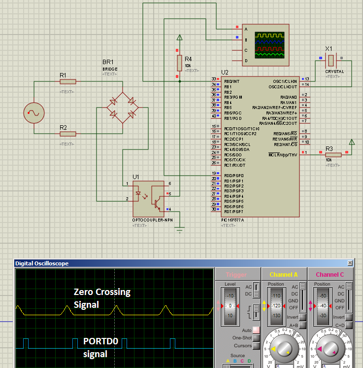
So, here I have explained a simple method of detecting zero crossing with PIC16F877A, employing only two or three resistors, a bridge rectifier and an optocoupler for the hardware portion of zero cross detection. 

The PIC 16F877A detects the zero crossing using the RB0/INT external interrupt function. I have explained how the zero cross is detected and how the PIC acts upon detection, below.


Fig. 1 - Schematic, zero crossing signal and RD0 signals

---------------------------------------------------------------------------------------------------------
Here is the code for PIC16F877A:
(You can download the source file from
https://rapidshare.com/files/604474700/ZeroCrossing.c )
---------------------------------------------------------------------------------------------------------
//Programmer: Syed Tahmid Mahbub
//Compiler: mikroC PRO for PIC v4.60
//Target PIC: PIC16F877A
//Program for zero-cross detection
//---------------------------------------------------------------------------------------------------------
unsigned char FlagReg;
sbit ZC at FlagReg.B0;

void interrupt(){
     if (INTCON.INTF){          //INTF flag raised, so external interrupt occured
        ZC = 1;
        INTCON.INTF = 0;
     }
}

void main() {
     PORTB = 0;
     TRISB = 0x01;              //RB0 input for interrupt
     PORTD = 0;
     TRISD = 0;                 //PORTD all output
     OPTION_REG.INTEDG = 0;      //interrupt on falling edge
     INTCON.INTF = 0;           //clear interrupt flag
     INTCON.INTE = 1;           //enable external interrupt
     INTCON.GIE = 1;            //enable global interrupt
    
     while (1){
           if (ZC){ //zero crossing occurred
              PORTD.B0 = 1; //Send a 1ms pulse
              delay_ms(1);
              PORTD.B0 = 0;
              ZC = 0;
           }
     }
}
---------------------------------------------------------------------------------------------------------

Explanation:


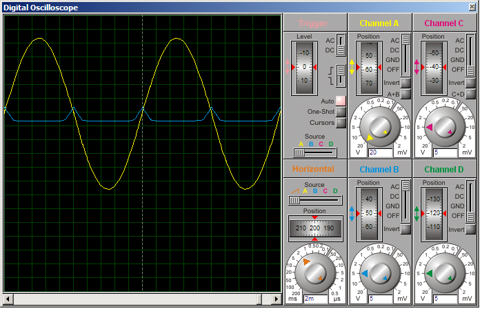
     Fig. 2
     Yellow - AC signal
     Blue - signal on RB0

In yellow (in Figure 2), you can see the input AC voltage (sinusoidal waveform). BR1 rectifies this AC voltage to DC, but since there is no bulk smoothing capacitor, the output is not pure DC, but pulsating DC as shown below.

Fig. 3- The rectified pulsating DC

The output of the bridge rectifier BR1 is DC and current through optocoupler is limited by resistors R1 and R2 (you may use a single resistor instead of 2 if you want, but using 2 resistors distributes the power dissipation and thus generates less heat and lower power per resistor).

So, the optocoupler LED stays on for most of the cycle except when the AC sine wave "crosses zero" (is around zero). While the optocoupler LED is on, the transistor is on and so pulls pin RB0 of PIC16F877A low.

PIC16F877A is coded to enable the external interrupt. An interrupt is generated upon the falling edge of RB0. The diagram below will illustrate what I mean by falling edge.

       Fig.4
       Yellow - signal on RB0
       Blue - signal from RD0

During most of the cycle, the optocoupler LED is on and so RB0 is low. When the optocoupler LED is off as the AC wave is about to cross "zero", RB0 goes high. The transition from low to high on RB0 is a rising edge. When the optocoupler LED is then again turned on as the AC wave crossed the "zero" level (zero crossing), RB0 goes low. This transition from high to low is a falling edge. And upon a falling edge, an interrupt is generated.

When an interrupt is generated, the ZC flag is set (see code above). In the main code, ZC flag is always checked (this is called polling a flag). When ZC flag is set (zero crossing occurred), a 1ms pulse is generated on RD0 (PORTD0) and then the ZC flag is cleared. For example's sake, I have produced a 1ms pulse. You can do whatever you want upon zero-cross detection. The ZC flag is then again continuously polled to check for next interrupt.

You can see all this illustrated in Figures 2, 3 and 4 above.

Oct 25, 2012

Temperature Sensor (MCP9700 + PIC16F877A)


Here's a temperature sensor (thermometer) circuit that you can easily build. It uses the popular PIC 16F877A microcontroller. The temperature sensor is MCP9700. The MCP9700 outputs an analog voltage corresponding to the temperature. The PIC reads the analog voltage, processes it and displays temperature on the LCD. The temperature range of this circuit is -40'C to +125'C.

The methods of processing the output of the MCP9700 can be found in the datasheet: ww1.microchip.com/downloads/en/devicedoc/21942a.pdf 

The analog to digital conversion is done by the PIC ADC module. In the code, I've used the mikroC library function for ADC. You can view the library file here: http://www.mikroe.com/download/eng/documents/compilers/mikroc/pro/pic/help/adc_library.htm

However, you should have a knowledge of how the ADC module works and how to use it. I had written a tutorial on modalities of operation of the PIC 16F877A ADC. You can find the tutorial here:
http://tahmidmc.blogspot.com/2012/03/modalities-of-using-adc-module-of.html

For LCD interfacing, I used the mikroC LCD library. You can view the library file here: http://www.mikroe.com/download/eng/documents/compilers/mikroc/pro/pic/help/lcd_library.htm

Here is the code for the PIC16F877A:

(You can download the source file from: https://rapidshare.com/files/4167495939/MC9700_Interface.c


--------------------------------------------------------------------------------------------------------------
//Programmer: Syed Tahmid Mahbub
//Compiler: mikroC PRO for PIC v4.60
//Target PIC: PIC16F877A
--------------------------------------------------------------------------------------------------------------
sbit LCD_RS at RB4_bit;
sbit LCD_EN at RB5_bit;
sbit LCD_D4 at RB0_bit;
sbit LCD_D5 at RB1_bit;
sbit LCD_D6 at RB2_bit;
sbit LCD_D7 at RB3_bit;

sbit LCD_RS_Direction at TRISB4_bit;
sbit LCD_EN_Direction at TRISB5_bit;
sbit LCD_D4_Direction at TRISB0_bit;
sbit LCD_D5_Direction at TRISB1_bit;
sbit LCD_D6_Direction at TRISB2_bit;
sbit LCD_D7_Direction at TRISB3_bit;


void main() {
     unsigned long int Temp;
     unsigned int ADRead;
     unsigned int vDisp[3];
     unsigned char Display[7];
     PORTA = 0;
     TRISA = 0X01;
     PORTB = 0;
     TRISB = 0;
     LCD_Init();
     LCD_Cmd(_LCD_CURSOR_OFF);
     LCD_Cmd(_LCD_CLEAR);
     LCD_Out(1, 1, "Temp:");
     //Display = "+125 'C";
     Display[4] = 39; //'
     Display[5]= 'C';
     ADCON1 = 0x0E;
     ADC_Init();
     while (1){
           ADRead = ADC_Get_Sample(0);
           if (ADRead > 102){// 'If temperature is positive
              Temp = (100 * ( (10 * ADRead) - 1024 ) ) >> 11; //'Get temperature
              Display[0] = '+';
           }
           else{ // 'If temperature is negative
              Temp = ( (1024 - (10 * ADRead) ) * 100 ) >> 11; //'Get temperature
              Display[0] = '-';
           }
           vDisp[0] = Temp / 100;
           vDisp[1] = (Temp / 10) % 10;
           vDisp[2] = Temp % 10;
           Display[1] = vDisp[0] + 48;
           Display[2] = vDisp[1] + 48;
           Display[3] = vDisp[2] + 48;
           LCD_Out(1, 8, Display); // 'Show temperature
     }
}
 --------------------------------------------------------------------------------------------------------------

Reference documents:

MCP9700 datasheet: ww1.microchip.com/downloads/en/devicedoc/21942a.pdf
PIC16F877A datasheet: ww1.microchip.com/downloads/en/devicedoc/39582b.pdf
mikroC LCD library: http://www.mikroe.com/download/eng/documents/compilers/mikroc/pro/pic/help/lcd_library.htm
mikroC ADC library: http://www.mikroe.com/download/eng/documents/compilers/mikroc/pro/pic/help/adc_library.htm
Modalities of Using the ADC module of the PIC 16F877A: http://tahmidmc.blogspot.com/2012/03/modalities-of-using-adc-module-of.html

Temperature Sensor (DS18S20 + PIC16F877A)


Here's a temperature sensor (thermometer) circuit that you can easily build. It uses the popular PIC 16F877A microcontroller. The temperature sensor is DS18S20. The DS18S20 communicates through the one-wire protocol. The PIC16F877A communicates with the DS18S20 with the one-wire protocol and gets the information for the temperature and displays it on the LCD.

The temperature range of this circuit is -55'C to +125'C.

The methods of communicating with the DS18S20 and sending/receiving commands, and reading the temperature value,  are all explained in the DS18S20 datasheet (datasheets.maximintegrated.com/en/ds/DS18S20.pdf).


Here is the code for the PIC16F877A:
(You can download the source file from: https://rapidshare.com/files/1817975964/DS18S20PIC16F877A.c)
--------------------------------------------------------------------------------------------------------------
//Programmer: Syed Tahmid Mahbub
//Compiler: mikroC PRO for PIC v4.60
//Target PIC: PIC16F877A
--------------------------------------------------------------------------------------------------------------

sbit LCD_RS at RB4_bit;
sbit LCD_EN at RB5_bit;
sbit LCD_D4 at RB0_bit;
sbit LCD_D5 at RB1_bit;
sbit LCD_D6 at RB2_bit;
sbit LCD_D7 at RB3_bit;

sbit LCD_RS_Direction at TRISB4_bit;
sbit LCD_EN_Direction at TRISB5_bit;
sbit LCD_D4_Direction at TRISB0_bit;
sbit LCD_D5_Direction at TRISB1_bit;
sbit LCD_D6_Direction at TRISB2_bit;
sbit LCD_D7_Direction at TRISB3_bit;

unsigned char TempH;
unsigned char TempL;
unsigned char TLow;
unsigned char vDisp[9];
unsigned char DP;

void main() {
     PORTB = 0;
     TRISB = 0;
     LCD_Init();
     LCD_CMD(_LCD_CURSOR_OFF);
     LCD_CMD(_LCD_CLEAR);
     PORTD = 0;
     TRISD = 0x01;
     delay_ms(200); //Wait for sensor and LCD to stabilize
     //vDisp = "+124.5 'C"
     vDisp[4] = '.';
     vDisp[7] = 39; // '
     vDisp[8] = 'C';
     LCD_Out(1,1, "Temp:");
     while (1){
         OW_Reset(&PORTD, 0); // 'Reset command to initialize One-Wire
         OW_Write(&PORTD, 0, 0xCC); // 'Skip ROM Command
         OW_Write(&PORTD, 0, 0x44); // 'Convert_T command
         delay_ms(800); // 'Provide delay for conversion
         RD7_bit = ~RD7_bit;
         OW_Reset(&PORTD, 0); // 'Reset command to initialize One-Wire
         OW_Write(&PORTD, 0, 0xCC); // 'Skip ROM Command
         OW_Write(&PORTD, 0, 0xBE); // 'Read Scratchpad Command
         TempL = OW_Read(&PORTD,0); //Read Temperature low byte
         TempH = OW_Read(&PORTD,0); //Read Temperature high byte
         DP = TempL & 0x01; // 'Check if Temperature is integer or fractional
         if (TempH){ //If reading is negative
            vDisp[0] = '-';
            TempL = ((~TempL) + 1) >> 1;
         }
         else{
             vDisp[0] = '+';
             TempL = TempL >> 1; // 'Shift one position right (divide by 2) to get integer reading and get rid of decimal point
         }
         vDisp[1] = (TempL / 100) + 48; // 'Get hundreds and convert to ASCII
         vDisp[2] = ((TempL / 10) % 10) + 48; // 'Get tens and convert to ASCII
         vDisp[3] = (TempL % 10) + 48; // 'Get units and convert to ASCII
         if (DP){ // 'If reading is fractional, ie has 0.5 at end
            vDisp[5] = '5';
         }
         else{ // 'If reading is a whole number
            vDisp[5] = '0';
         }
         Lcd_Chr(1,8, vDisp[0]);
         Lcd_Chr(1,9, vDisp[1]);
         Lcd_Chr(1,10, vDisp[2]);
         Lcd_Chr(1,11, vDisp[3]);
         Lcd_Chr(1,12, vDisp[4]);
         Lcd_Chr(1,13, vDisp[5]);
         Lcd_Chr(1,14, vDisp[6]);
         Lcd_Chr(1,15, vDisp[7]);
         Lcd_Chr(1,16, vDisp[8]);
     }
}
--------------------------------------------------------------------------------------------------------------
Reference documents:

DS18S20 datasheet: datasheets.maximintegrated.com/en/ds/DS18S20.pdf
PIC16F877A datasheet: ww1.microchip.com/downloads/en/devicedoc/39582b.pdf
mikroC LCD library: http://www.mikroe.com/download/eng/documents/compilers/mikroc/pro/pic/help/lcd_library.htm
mikroC One-Wire library: http://www.mikroe.com/download/eng/documents/compilers/mikroc/pro/pic/help/onewire_library.htm

Oct 24, 2012

Temperature Sensor (LM35 + PIC16F877A)


Here's one temperature sensor (thermometer) circuit that you can easily build. It uses the popular PIC 16F877A microcontroller. The temperature sensor is LM35. The LM35 outputs an analog voltage proportional to the temperature. The output from the LM35 is 0.1V/'C. So, when temperature sensed is 61'C, the output voltage is 0.61V. This analog voltage is read by the PIC and processed to display the corresponding temperature value on the LCD.

The temperature range for this circuit is 0'C to 150'C.

The analog to digital conversion is done by the PIC ADC module. In the code, I've used the mikroC library function for ADC. You can view the library file here: http://www.mikroe.com/download/eng/documents/compilers/mikroc/pro/pic/help/adc_library.htm

However, you should have a knowledge of how the ADC module works and how to use it. I had written a tutorial on modalities of operation of the PIC 16F877A ADC. You can find the tutorial here:
http://tahmidmc.blogspot.com/2012/03/modalities-of-using-adc-module-of.html

For LCD interfacing, I used the mikroC LCD library. You can view the library file here: http://www.mikroe.com/download/eng/documents/compilers/mikroc/pro/pic/help/lcd_library.htm


Here is the code for PIC16F877A:
(You can download the source file from: https://rapidshare.com/files/3044512089/LM35PIC16F877A.c)
--------------------------------------------------------------------------------------------------------------
//Programmer: Syed Tahmid Mahbub
//Compiler: mikroC PRO for PIC v4.60
//Target PIC: PIC16F877A
--------------------------------------------------------------------------------------------------------------
sbit LCD_RS at RB4_bit;
sbit LCD_EN at RB5_bit;
sbit LCD_D4 at RB0_bit;
sbit LCD_D5 at RB1_bit;
sbit LCD_D6 at RB2_bit;
sbit LCD_D7 at RB3_bit;

sbit LCD_RS_Direction at TRISB4_bit;
sbit LCD_EN_Direction at TRISB5_bit;
sbit LCD_D4_Direction at TRISB0_bit;
sbit LCD_D5_Direction at TRISB1_bit;
sbit LCD_D6_Direction at TRISB2_bit;
sbit LCD_D7_Direction at TRISB3_bit;

unsigned long ADRead;
unsigned int vDisp[3];
unsigned char Display[7];
    
void main() {

     PORTA = 0;
     TRISA = 0X01;
     PORTB = 0;
     TRISB = 0;
     LCD_Init();
     LCD_Cmd(_LCD_CURSOR_OFF);
     LCD_Cmd(_LCD_CLEAR);
     LCD_Out(1, 1, "Temp:");
     //Display = "+125 'C";
     Display[4] = 39; //'
     Display[5]= 'C';
     ADCON1 = 0x0E;
     ADC_Init();
     while (1){
           ADRead = (ADC_Get_Sample(0) * 500) >> 10;
           vDisp[0] = ADRead / 100;
           vDisp[1] = (ADRead / 10) % 10;
           vDisp[2] = ADRead % 10;
           Display[1] = vDisp[0] + 48;
           Display[2] = vDisp[1] + 48;
           Display[3] = vDisp[2] + 48;
           LCD_Chr(1, 8, Display[0]);
           LCD_Chr(1, 9, Display[1]);
           LCD_Chr(1, 10, Display[2]);
           LCD_Chr(1, 11, Display[3]);
           LCD_Chr(1, 12, Display[4]);
           LCD_Chr(1, 13, Display[5]);
           //LCD_Out(1, 8, ); // 'Show temperature
           delay_ms(200); //200ms delay for waiting
     }
}
--------------------------------------------------------------------------------------------------------------

Reference documents:
LM35 datasheet: www.ti.com/lit/ds/symlink/lm35.pdf
PIC16F877A datasheet: ww1.microchip.com/downloads/en/devicedoc/39582b.pdf
Modalities of Using the ADC module of the PIC16F877A: http://tahmidmc.blogspot.com/2012/03/modalities-of-using-adc-module-of.html
mikroC LCD library: http://www.mikroe.com/download/eng/documents/compilers/mikroc/pro/pic/help/lcd_library.htm
mikroC ADC library: http://www.mikroe.com/download/eng/documents/compilers/mikroc/pro/pic/help/adc_library.htm

Oct 21, 2012

MAGIC of knowledge


I turned the switch on and BOOM! That noise, the tiny puff of smoke and the accompanying smell had become far too familiar.

I looked on in confusion at all the failed electronics components in front of me. I needed answers. Why did the H-bridge circuit not work as “claimed”? Books showed numerous such circuits. The Internet was not short of designs either. They were all similar though. I had done my research. I thought I understood the principles and modalities of operation. Then, where did the fault lie? Frustration was creeping in. But I just had to find the fault and fix it.

I wanted to make the SMPS based inverter because I could learn so much in a field completely new to me and then use the inverter at home during power cuts. In that one night of experimentation, I had failed repeatedly, damaging 24 IR2110’s and a lot more components. I had applied all I had learned thus far. Success, however, eluded me.


After repeated failures, I posted my problem on online electronics forums. Numerous members from around the world, engineers and non-engineers alike, joined in to contribute. I learnt and questioned. Heated discussions, arguments and counter-arguments took place. And I absorbed all I could. I did not get a direct solution to my problem but I felt I had become richer and perhaps, through discussion, helped make others richer.

 I spent hours reading documents and application notes, analyzing existing designs and testing the different concepts experimentally. However, the result was the same.

One day I stumbled upon a circuit on the internet, which had a different type of MOSFET gate protection, which employed a resistor between “gate” and “source”. Theoretically this resistor was not required. I redesigned the entire circuit with these resistors connected.

MAGIC! I got the required AC output. No BOOM, no smoke, no smell! 4 resistors (one between gate and source of each MOSFET) that, in total, cost less than $0.25, had been the difference! This was the magic of knowledge – the power of knowledge people refer to.

I then resorted to books and the Internet and learnt why the gate-to-source resistor stopped the MOSFET, and in turn the driver IR2110, from “blowing”.

After completing my inverter, I regularly posted on online electronics forums, especially www.edaboard.com – in the time I found between school, sports, electronics endeavors and other activities – to help others and to learn.

Many people later posted on www.edaboard.com regarding problems where the MOSFET and driver “blew”. I had been the one to suggest the use of the “gate-to-source” resistor and this had been the solution to most such problems.

My repeated failures had frustrated me, but also pushed me beyond the boundary of books to learn, acquire and share knowledge, to believe in the power of knowledge but most importantly to believe in myself and my capabilities. This belief and these teachings helped me in later endeavors to overcome obstacles in my way and achieve success.

---------------------------------------------------------------------------------------------------------------------
Importance of the gate-to-source resistor:

It prevents accidental turn on of the MOSFET by external noise usually at startup when the gate is floating. The MOSFET may sometimes turn on with a floating gate because of the internal drain to gate "Miller" capacitance. A gate to source resistor acts as a pull-down to ensure a low level for the MOSFET. I have had MOSFETs blowing up in high voltage circuits, without the resistor in place. In most of the commercial power supplies / inverters I have seen, there is a 1k resistor used.

A similar experience is narrated in Sanajaya Maniktala's "Switching Power Supplies A to Z". This is also talked of in Raymond Mack's "Switching Power Supplies Demystified".

Oct 10, 2012

Smart Sine - Software to generate sine table


There is an updated Python version of this now available, along with source code: https://tahmidmc.blogspot.com/2023/11/smartsinepy-and-example-of-gui.html

Here is the software Smart Sine, that I created and now use to generate sine tables.

It is the improved and more developed version of the software I had previously created with a few more useful features. It is relatively simple to use and gives results quickly as opposed to manually calculating the table.

If the software asks for .NET Framework Installation, you can download it from:


or


Download the software from :

Recommended:
https://drive.google.com/file/d/0B4SoPFPRNziHWVdLYVFKeHlsWjQ/view?usp=sharing


Here are a few screenshots:


Generation of sine wave using SPWM in PIC16F684


I have previously shown how to calculate the values for the sine table. Now I will show you how to use that sine table for generating a sine wave using a PIC16F684. Why PIC16F684? It is a nice little 14-pin PIC that contains all that is needed for SPWM (sinusoidal pulse width modulation) – the ECCP module. Since the ADC or comparator or other peripherals are not used and there are enough pins, I selected the PIC16F684.


Let’s run the 16F684 from a 16MHz crystal oscillator and use a 16kHz switching frequency.
So, the required value of PR2 is 249.

The sine table (for half a cycle) is:
0, 25, 49, 73, 96, 118, 139, 159, 177, 193, 208, 220, 231, 239, 245, 249, 250, 249, 245, 239, 231, 220, 208, 193, 177, 159, 139, 118, 96, 73, 49, 25
'''''''''''''''''''''''''''''''''''''''''''''''''''''''''''''''''''''''''''''''''''''''''''''''''''''''''''''''''''''''''''''''''''''''''''''''''''''''''''''''''''''''''''''''''''''''''''''''''''''''''''''''''''''''''''''''''''''''''''''''''''''''''''''''''''''''''''''''''''''''''''''''''''''''''''''''''''''''''''''''''''''''''''''''''''''''''''''''''''''''''''''''''''''''''''''''''''''''''''''''''''''''''''''''''''''''''''
Here is the code:

unsigned char sin_table[32]={0,25,49,73,96,118,137,
159,177,193,208,220,231,239,245,249,250,249,245,
239,231,220,208,193,177,159,137,118,96,73,49,25};


unsigned int TBL_POINTER_NEW, TBL_POINTER_OLD, TBL_POINTER_SHIFT, SET_FREQ;
unsigned int TBL_temp;
unsigned char DUTY_CYCLE;

void interrupt(){
     if (TMR2IF_bit == 1){
        TBL_POINTER_NEW = TBL_POINTER_OLD + SET_FREQ;
        if (TBL_POINTER_NEW < TBL_POINTER_OLD){
           CCP1CON.P1M1 = ~CCP1CON.P1M1; //Reverse direction of full-bridge
        }
        TBL_POINTER_SHIFT = TBL_POINTER_NEW >> 11;
        DUTY_CYCLE = TBL_POINTER_SHIFT;
        CCPR1L = sin_table[DUTY_CYCLE];
        TBL_POINTER_OLD = TBL_POINTER_NEW;
        TMR2IF_bit = 0;
     }
}

void main() {
     SET_FREQ = 410;
     TBL_POINTER_SHIFT = 0;
     TBL_POINTER_NEW = 0;
     TBL_POINTER_OLD = 0;
     DUTY_CYCLE = 0;
     ANSEL = 0; //Disable ADC
     CMCON0 = 7; //Disable Comparator
     PR2 = 249;
     TRISC = 0x3F;
     CCP1CON = 0x4C;
     TMR2IF_bit = 0;
     T2CON = 4; //TMR2 on, prescaler and postscaler 1:1
     while (TMR2IF_bit == 0);
     TMR2IF_bit = 0;
     TRISC = 0;
     TMR2IE_bit = 1;
     GIE_bit = 1;
     PEIE_bit = 1;
    
     while(1);
}
'''''''''''''''''''''''''''''''''''''''''''''''''''''''''''''''''''''''''''''''''''''''''''''''''''''''''''''''''''''''''''''''''''''''''''''''''''''''''''''''''''''''''''''''''''''''''''''''''''''''''''''''''''''''''''''''''''''''''''''''''''''''''''''''''''''''''''''''''''''''''''''''''''''''''''''''''''''''''''''''''''''''''''''''''''''''''''''''''''''''''''''''''''''''''''''''''''''''''''''''''''''''''''''''''''''''''

Download the hex file from:
http://www.4shared.com/file/PlETv7nt/SPWM684.html
https://rapidshare.com/files/3811707712/SPWM684.hex

To make the process of updating sine table value simple, table pointer was used. The frequency here is set to 50Hz and the switching frequency is 16kHz. The 16F684 generates SPWM signals on P1A, P1B, P1C and P1D pins which should then be connected to a full-bridge stage for feeding into transformer.

16kHz frequency is used since it is toward the end of the audible spectrum and so the noise emitted will not be intolerable. Frequency above 20kHz is not used as 20kHz is the maximum frequency for the ECCP module of 16F684.

Since the ECCP module and interrupt take care of the SPWM, it is being executed by the hardware modules. So, while these are running, you can do other stuff as well by coding them in the while(1) loop, which, as you can see, is blank now, since no other task is being carried out besides SPWM.

Generating the sine table:

The SPWM signals:

The generated sine wave:

Oct 9, 2012

600W 50Hz sine wave inverter test circuit


Here I tested a 600W 50Hz sine wave inverter circuit using push-pull topology instead of full-bridge topology. 2 PIC16F684's were used - one for SPWM and one for charging. 2 microcontrollers were used intentionally as the purpose was to test if I could use the microcontrollers together and use each of them for multitasking. 2 auxiliary transformers are used - one for powering the circuitry when running off mains and one for current sensing. Charging is done with 4 relays that are turned on/off according to input voltage and accordingly connect the input voltage to an appropriate transformer winding/tapping to keep output voltage relatively constant. Switching frequency is 16kHz. The sine table has 32 values.

Here is the complete sine table:

0, 16, 32, 47, 62, 77, 91, 103, 115, 126, 136, 144, 151, 156, 160, 162, 163, 162, 160, 156, 151, 144, 136, 126, 115, 103, 91, 77, 62, 47, 32, 16, //65%

0, 17, 33, 49, 65, 80, 94, 107, 120, 131, 141, 149, 156, 162, 166, 168, 169, 168, 166, 162, 156, 149, 141, 131, 120, 107, 94, 80, 65, 49, 33, 17, //67.5%

0, 17, 34, 51, 67, 82, 97, 111, 124, 135, 146, 154, 162, 167, 172, 174, 175, 174, 172, 167, 162, 154, 146, 135, 124, 111, 97, 82, 67, 51, 34, 17, //70%

0, 18, 35, 53, 69, 85, 101, 115, 128, 140, 150, 160, 167, 173, 178, 180, 181, 180, 178, 173, 167, 160, 150, 140, 128, 115, 101, 85, 69, 53, 35, 18, //72.5%

0, 18, 37, 55, 72, 89, 104, 119, 133, 145, 156, 166, 174, 180, 184, 187, 188, 187, 184, 180, 174, 166, 156, 145, 133, 119, 104, 89, 72, 55, 37, 18, //75%

0, 19, 38, 56, 74, 91, 108, 123, 137, 150, 161, 171, 179, 186, 190, 193, 194, 193, 190, 186, 179, 171, 161, 150, 137, 123, 108, 91, 74, 56, 38, 19, //77.5%

0, 20, 39, 58, 77, 94, 111, 127, 141, 155, 166, 176, 185, 191, 196, 199, 200, 199, 196, 191, 185, 176, 166, 155, 141, 127, 111, 94, 77, 58, 39, 20, //80%

0, 20, 40, 60, 79, 97, 114, 131, 146, 159, 171, 182, 190, 197, 202, 205, 206, 205, 202, 197, 190, 182, 171, 159, 146, 131, 114, 97, 79, 60, 40, 20, //82.5%

0, 21, 42, 62, 82, 100, 118, 135, 151, 165, 177, 188, 197, 204, 209, 212, 213, 212, 209, 204, 197, 188, 177, 165, 151, 135, 118, 100, 82, 62, 42, 21, //85

0, 21, 43, 64, 84, 103, 122, 139, 155, 169, 182, 193, 202, 210, 215, 218, 219, 218, 215, 210, 202, 193, 182, 169, 155, 139, 122, 103, 84, 64, 43, 21, //87.5%

0, 22, 44, 65, 86, 106, 125, 143, 159, 174, 187, 198, 208, 215, 221, 224, 225, 224, 221, 215, 208, 198, 187, 174, 159, 143, 125, 106, 86, 65, 44, 22, //90%

0, 23, 45, 67, 88, 109, 128, 147, 163, 179, 192, 204, 213, 221, 227, 230, 231, 230, 227, 221, 213, 204, 192, 179, 163, 147, 128, 109, 88, 67, 45, 23, //92.5%

0, 23, 46, 69, 91, 112, 132, 151, 168, 184, 198, 210, 220, 228, 233, 237, 238, 237, 233, 228, 220, 210, 198, 184, 168, 151, 132, 112, 91, 69, 46, 23 //95%

//0, 25, 49, 73, 96, 118, 139, 159, 177, 193, 208, 220, 231, 239, 245, 249, 250, 249, 245, 239, 231, 220, 208, 193, 177, 159, 139, 118, 96, 73, 49, 25, //100%

Each 32 values corresponds to one half-cycle of a 50Hz sine wave, each set corresponding to a different duty cycle. The duty cycle varies as the amplitude of the sine wave is varied by adjusting the value of the CCPR1L register. The maximum value of each set of 32 values is set to correspond to a different duty cycle and the other 31 values are in the same ratio to the maximum value for all sets of values. A pointer is used in the main code to retrieve the required set of 32 values for a required duty cycle. The lowest duty cycle is 65% because, for feedback, lower duty cycles are not required. The maximum duty cycle is set at 95% to provide some dead-time and avoid cross-conduction. At the beginning of each half-cycle, one MOSFET is driven according to the duty cycle values retrieved from the table. At the end of the half-cycle and beginning of the next half-cycle, the other MOSFET is driven according to those same duty cycle values. Upon a fault condition (such as low-battery), both MOSFETs are turned off and kept off.

It works as intended and testing was successful. However, it requires adjustments to be made for the final one.

Oct 8, 2012

SMPS TopoMagic


When I started learning about and designing SMPS circuits in 2008, I read from various books and online resources – application notes, reference manuals, design notes, design tips, circuit designs and various tutorials. I understood most of the concepts. But the mathematics was complex and there were so many formulae and calculations. They were not all present in any single book or document. Making all the necessary calculations using the different formulae available in all the different documents was difficult, tiring and cumbersome.

While I was learning SMPS and started getting a hold of the basics, I was learning Visual Basic at school. During the mid-year school break, I learnt from various tutorials online and practiced during the school vacation to develop my Visual Basic skills. After I learnt most of the basics, I decided to put my skills to the test. It would be good practice and I could make a useful program in the process.

I started coding using the information present in various books and online resources to create the software “SMPS TopoMagic” to help me with the calculations necessary for SMPS circuits employing the flyback, push-pull, half-bridge and full-bridge topologies. After days of coding and debugging, “SMPS TopoMagic” was ready.

I knew that the software was far from perfect. As a student of class VIII, I did not understand many of the associated mathematics and had to occasionally resort to rough estimates and my lessons from hands-on test-and-trial. But it served my purpose.


Here's a little description about the software:


Let's use it for a push-pull design (click on image to enlarge it):


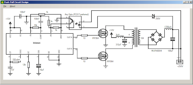
Here's the generated circuit (click on image to enlarge it):


Let's design a circuit with half-bridge converter (click on image to enlarge it):

Here's the generated circuit (click on image to enlarge it):

Let's use the software for a full-bridge design (click on image to enlarge it):

Here's the generated circuit (click on image to enlarge it):


Still I am learning SMPS, but when I gain enough expertise in SMPS, I want to incorporate that knowledge and expertise into this software so that it can be complete and perfect. Then, I hope to upload it online so that anyone can use it for his/her own SMPS circuit designs.