
Zero crossing detection with PIC16F877A
Zero crossing detection is very important, especially in power control circuits employing thyristors.
I have come across many people struggling with zero crossing detection with PIC microcontroller and thus they cannot fire triacs or SCRs as required.
So, here I have explained a simple method of detecting zero crossing with PIC16F877A, employing only two or three resistors, a bridge rectifier and an optocoupler for the hardware portion of zero cross detection.
The PIC 16F877A detects the zero crossing using the RB0/INT external interrupt function. I have explained how the zero cross is detected and how the PIC acts upon detection, below.
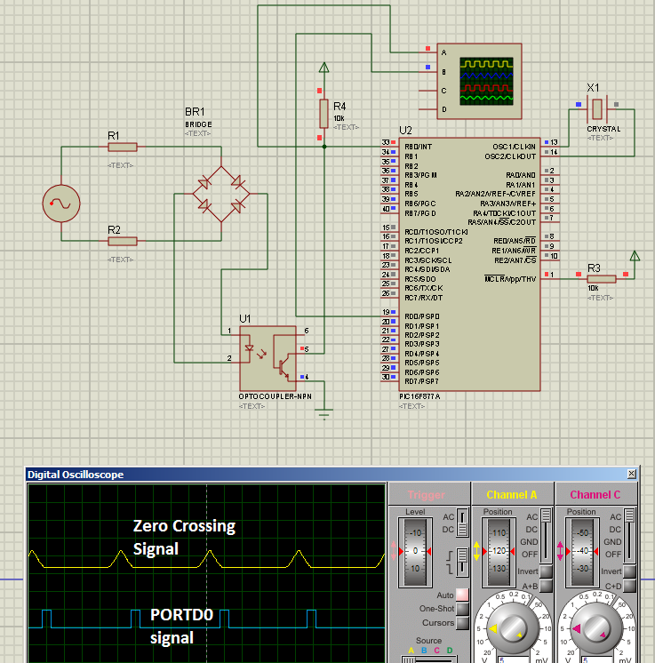
Fig. 1 - Schematic, zero crossing signal and RD0 signals
---------------------------------------------------------------------------------------------------------
Here is the code for PIC16F877A:
(You can download the source file from
https://rapidshare.com/files/604474700/ZeroCrossing.c )
---------------------------------------------------------------------------------------------------------
//Programmer: Syed Tahmid Mahbub
//Compiler: mikroC PRO for PIC v4.60
//Target PIC: PIC16F877A
//Program for zero-cross detection
//---------------------------------------------------------------------------------------------------------
unsigned char FlagReg;
sbit ZC at FlagReg.B0;
void interrupt(){
if (INTCON.INTF){ //INTF flag raised, so external interrupt occured
ZC = 1;
INTCON.INTF = 0;
}
}
void main() {
PORTB = 0;
TRISB = 0x01; //RB0 input for interrupt
PORTD = 0;
TRISD = 0; //PORTD all output
OPTION_REG.INTEDG = 0; //interrupt on falling edge
INTCON.INTF = 0; //clear interrupt flag
INTCON.INTE = 1; //enable external interrupt
INTCON.GIE = 1; //enable global interrupt
while (1){
if (ZC){ //zero crossing occurred
PORTD.B0 = 1; //Send a 1ms pulse
delay_ms(1);
PORTD.B0 = 0;
ZC = 0;
}
}
}
---------------------------------------------------------------------------------------------------------
Explanation:
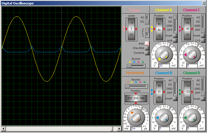
Fig. 2
Yellow - AC signal
Blue - signal on RB0
In yellow (in Figure 2), you can see the input AC voltage (sinusoidal waveform). BR1 rectifies this AC voltage to DC, but since there is no bulk smoothing capacitor, the output is not pure DC, but pulsating DC as shown below.

Fig. 3- The rectified pulsating DC
The output of the bridge rectifier BR1 is DC and current through optocoupler is limited by resistors R1 and R2 (you may use a single resistor instead of 2 if you want, but using 2 resistors distributes the power dissipation and thus generates less heat and lower power per resistor).
So, the optocoupler LED stays on for most of the cycle except when the AC sine wave "crosses zero" (is around zero). While the optocoupler LED is on, the transistor is on and so pulls pin RB0 of PIC16F877A low.
PIC16F877A is coded to enable the external interrupt. An interrupt is generated upon the falling edge of RB0. The diagram below will illustrate what I mean by falling edge.

Yellow - signal on RB0
Blue - signal from RD0
During most of the cycle, the optocoupler LED is on and so RB0 is low. When the optocoupler LED is off as the AC wave is about to cross "zero", RB0 goes high. The transition from low to high on RB0 is a rising edge. When the optocoupler LED is then again turned on as the AC wave crossed the "zero" level (zero crossing), RB0 goes low. This transition from high to low is a falling edge. And upon a falling edge, an interrupt is generated.
When an interrupt is generated, the ZC flag is set (see code above). In the main code, ZC flag is always checked (this is called polling a flag). When ZC flag is set (zero crossing occurred), a 1ms pulse is generated on RD0 (PORTD0) and then the ZC flag is cleared. For example's sake, I have produced a 1ms pulse. You can do whatever you want upon zero-cross detection. The ZC flag is then again continuously polled to check for next interrupt.
You can see all this illustrated in Figures 2, 3 and 4 above.


nice post. can i get ur contact no.
ReplyDeleteThanks.
ReplyDeleteSend me an email at my email address inferno (dash) rage (at) hotmail (dot) com.
Or give me your email address.
And I'll give you my contact number.
My email address u27409156@tuks.co.za
Deletereply me by email :mohankrishnaejjagiri@gmail.com
DeleteHi Tahmid
ReplyDeleteReally great work. Keep it up!
Ur work has been very helpful, Thank you.
Thanks!
DeleteI hope my work can help many others like you.
Regards,
Tahmid.
Tahmid,
ReplyDeleteYour explanation is very eloborate, yet very simple.
Thanks buddy.
Mitz
You're welcome. I'm glad I could be of help!
DeleteRegards,
Tahmid.
hi tahmid
ReplyDeletei want to know about you oscilloscope . is it a multichannel cro software ?
where from can i get it.
It's the digital oscilloscope in Proteus. It's part of the simulation software.
DeleteRegards,
Tahmid.
tahmid
ReplyDeletewhat is the bootstrap capacitor voltage rating.?
=high side mosfet rail voltage + vcc ? or low values can be applied ?
I assume you're talking about a high-side bootstrap-based drive circuit.
Deletehttp://tahmidmc.blogspot.com/2013/01/using-high-low-side-driver-ir2110-with.html
It has to withstand the low voltage only as it is charged to (VCC - VB) and is discharged for gate driving.
Use a voltage rating at least 1.5 times the VCC level. That should be fine.
Regards,
Tahmid.
ok thanks,
ReplyDeletebut i have a question about the mosfet switches that
you are connecting load between the two legs of mosfet
and at a time only one leg (upper and lower mosfet of same leg) are working and second one is off.....then current will flow where to where.....or what is the direction of current...
i have asked this question also in edaboard but till date there is no reply.. please explian the mosfet switch operation in detail ...i am confused so much.... TILL DATE..
if u r comfortable than we can voice chat on gmail..
captain.shahid.khan@gmail.com
First you should read up on full-bridge (also known as H-bridge) topology. Then you can feel free to ask any questions/doubts you have.
DeleteAssalam o Alaikum tahmid
ReplyDeletei need to ask you something. I am working on a back to back thyristor firing mechanism. I have a PIC18f452 microcontroller board which is powered by a 9V adapter. i am making a zero cross detector circuit by a transformer to step down the 220V to 12V and then feeding to it bridge and repeating the same thing that you did( i.e. bridge rectifier and optocoupler etc.)
my question is that do i need to make the ground of the zero-cross detector circuit common with the ground of the microcontroller board. i.e. shall i put a jumper wire between ground pin of 7805 IC on the microcontroller board and the ground of the bridge rectifier on the zero cross detector????
i am currently on the simulations but i have bought the components and will make the hardware after 2 days. i am just worried coz i can't buy the components again due to high prices. it would be very great if you help me in this regard... so that i could not end up burning the components or anything like that :)
anxiously waiting for your reply.
regards,
syed husnain
hai thamid , which is best simulation software (like matlab,orcad...)
ReplyDeleteFor electronics (especially PIC/AVR microcontrollers), I would say Proteus. But then again, I haven't used any other simulator and Proteus works brilliant!
DeleteRegards,
Tahmid.
TANK U VERY MUCH ENGR TAHMED, AM GRATEFUL, MY EMAIL IS ogbuuhenry@gmail.com
ReplyDeletepls i need ur contact and email, i still need ur help in many in this field of study, just a young student in university.
tanks alot more
ReplyDeletecan you please show the steps like configuring sine signal - 220v , 50 hz, and configuring other devices.
ReplyDeleteyou have used Mikro PIC compiler, could you show some steps, how to add a compiler or like that things, i am stuck after designing the circuit, so please tell if need to modify any value or any other info
You can get some details on the sine wave settings here: http://tahmidmc.blogspot.com/2013/02/demystifying-use-of-table-pointer-in.html
DeleteDear Tahmid..Can we control RPM of AC Motor with +-1 RPM Accuracy. I have a Single Phase shaded Pole AC Motor. Can we achieve this accuracy using Control loop and TRIAC Method.
ReplyDeletethank you so much..!! you can connect circuit zero cross to PWM modul of PIC16f877A to control brightness for Incandescent bulbs operate at 220VAC - 50Hz. And use to change the opening angle of Triac...??-- Can u help me..?? Because I need it for my projects.
ReplyDeleteYou can't use the regular PWM (as found in the CCP module of the PIC) for controlling the triac and bulb at 50Hz. You'll need to implement phase angle control or pulse skipping modulation in software. Take a look here:
DeleteAC Power Control with Thyristor: Phase Angle Control using triac with PIC16F877A:
http://www.tahmidmc.blogspot.com/2013/06/power-control-with-thyristor-phase.html
AC Power Control with Thyristor: Pulse Skipping using triac with PIC16F877A:
http://tahmidmc.blogspot.com/2013/06/ac-power-control-with-thyristor-pulse.html
Regards,
Tahmid.
Thank Tahmid so much..!!!!! sites you've shared to help me a lot.
DeleteThis comment has been removed by the author.
ReplyDeletetahmid i visit your blog everyday and am always loving it ...on SMPS how can i calculate my inductor value when winding because i dont have the inductor meter . can you explain how i can build it because am very good in embedded system programming. pls reply in my email at "microprogrammer@ymail.com" thanks
ReplyDeleteMr. Tahmid
ReplyDeletethank you tuor lesson was very helpfu;; thank you very much but i want ask you a q please
in the Schematic, zero crossing signal and RD0 signals before the bridge can i use 220 volt or i have to reduse it to 9v ????
My Email Is ameenyaghshy@gmail.com
Ameen
It can be 220V or it can be 9V. You just have to set the resistors accordingly. So, if you want, you can use 220V. Just use appropriate valued resistors to limit the current and choose resistors with sufficient power rating.
DeleteSyed
ReplyDeleteI have taken the liberty to refer to your page from my instructables page on making an AC dimmer.
My software is centered around an Arduino, but as the circuit can just as well be used by any other microcontroller, I presumed some of my readers would be interested in your article.
http://www.instructables.com/id/Arduino-controlled-light-dimmer-The-circuit/
That's pretty cool! :)
Deletelink not found pls put the new link.
ReplyDeleteAssalamualaikum Tahmid vai...ur code with 16f877a works great.
ReplyDeletei tried it for 18f4550,,,,,,but problem with this command...
OPTION_REG.INTEDG = 0;
i tried but couldn't fix it,,,,,any help!!!
btw.....my project regards a "power factor meter".........for which i need a zero level detector.
Regards...
That bit is to select the triggering edge for external interrupt. You need to find the equivalent for the 18F4550. You should go through the 18F4550 datasheet.
DeleteVery Useful. Thank you very much
ReplyDeleteis a great help to all, I could go through the code for the simulation and, Thanksgiving and successes, my email is brillit_057@hotmail.com or jbernaolacampos@gmail.com
ReplyDeleteis a great help to all, I could go through the code for the simulation and, Thanksgiving and successes, my email is brillit_057@hotmail.com or jbernaolacampos@gmail.com
ReplyDeleteThis comment has been removed by a blog administrator.
ReplyDeleteআমি আগে কাউকে এতো সহজ করে zero crossing detection বোঝাতে দেখিনি! খুব সহজেই বুঝে গেলাম! thank you so much! আমি triac দিয়ে AC fan speed controller বানাতে চাই। zero crossing detect করে সেটা কিভাবে করবো তা একটু বুঝিয়ে দেবেন প্লিজ? অনেকে কমপ্লেইন করে যে এভাবে light dimmer অথবা fan speed regulator বানালে তা ঠিক মত কাজ করছেনা, মানে ঠিকমত বাড়ছে- কমছেনা। এই সমস্যাটা কি কারনে হতে পারে?
ReplyDeleteVery impressive blog. Found it today from google while searching for zero crossing.
ReplyDeleteSir, I have two AC power sources. At present I have an analog logic circuit to shift from one AC source to another using a relay or triac.
Now I wish to use zero cross detect for this purpose. Please help me out if you can.
I have understood the concept but ain't able to figure out how to proceed.
arunsingh911@gmail.com
Hello
ReplyDeleteI have been trying to work on this.But I couldnt get the proper output.If you have the source code and also the Proteus file is it possible to mail it?If yes I will share my email ID
i need ups technology,can you help me
ReplyDeleteHi Tahmid
ReplyDeleteMany thanks for the info, your blog is really helpful!
May I ask you a question? Which optocoupler would you recommend for a zero crossing detector implemented in a 230 VAC Line?
Regards,
Gabriel
Hi tehmid
ReplyDeleteBrother can you please tell me which optocoupler should I use ??
Regards
Rahul
rahulahuja.eng @gmail.com
A standard optocoupler like the 4N35 should be good. When choosing an optocoupler consider the effect of the CTR.
DeleteHi Tahmid
DeleteThanks for your reply. Can you also suggest me the values of R1 & R2 ?? Actually I am a mechanical Engg. and don't know much about electronics.
Thanks & Regards
Rahul
Hi Tamid Nice post can u pls send ur mail id to my mail id samathasan1@gmail.com currently i am working on ZCD .
DeleteHow can the same be done using 18F4550? What will be the required changes? My project concerns with the triggering of MOSFETs.
ReplyDeleteHi Tehmid
ReplyDeleteI tried the circuit as you have shown using 8051 controller and triggring BTA12 using moc3021 and speed is also getting reduced. But I am facing one problem. My fan is flickering (giving jerks). I tried a lot my changing the time of triggering and duration between triggering and zcd but unable to solve this problem. Please suggest me what to do ??
Hi Tahmid,
ReplyDeleteI found your blog very useful for my project. I used the zero crosspoint to fire the triac to drive an ac induction motor. WE are 60 Hz which means we have 60 cylces per second. My concern is I want to fire the triac on for the first 4cyle and then off for the next 1cyle then On again for the next 4cyles and off for the next one cyle ......and continue this process. which means Im going to chop that 60Hz (60 cyle). how are we going to do that? because unlike your program above its output is choping every cycle. this on and off must be done during the Zero crossing to avoid a noise in the power line, that's why using a delay is not applicable because of the timing of the ON and Off. ON and off must be done during zero crossing.
Hi Tahmid
ReplyDeletei would like to upload the source file but i cant.
Tahmid brother please help me,i wanted take project on your inverter ckt in my final year project. I am worked around your blog over one month. but i did n't find out the schematic circuit diagram diagram. so please kind to the link (or) file to gmail account named sairampaidissetty@gmail.com. or at least reply me as soon as possible. i am witting for reply
ReplyDeletehi tahmid
ReplyDeletei want to use zero crossing detector for triggering scr. i am using potentiometer adc but i didn't succeed.please communicate with me.
can any one share the source file of this?
ReplyDeleteas there is a problem with this source code for downloading it.there fore please help me for providing me the source code with mplab software version.
ReplyDeletethanks
I built a simiar circuit using AVR micro,4n25,MOC3021,BTA16 and the fan speed is controlled in 5 different steps(namely-0,1,2,3,4).In 0,the micro is switching off the MOC3021 so the output is 0.Also in '4',the output of the micro is continuously giving '1',so that the MOC3021 stays on and the fan rotates in full speed.The speed control is done in 1,2 & 3.The speed control works perfectly on pure sine wave AC.But whenever electricity goes off and Inverter power takes place,the speed control malfunctions(Either the fan stops or it generates great hum and rotates very slowly).I saw with a DSO that the inverter is giving square wave output.My question is,is this normal for the circuit to malfunction in square wave(zero cross is happening in square wave also so why is it malfunctioning??)or I am missing something??There is also external snubber attached using 39R and .01uF.Any help is appreciated....Please reply soon.
ReplyDeletesir may i know what simulation software you use on this project, can you simulate pic program on this software?
ReplyDeleteGOOd work sir
ReplyDeleteNeed HELP
ReplyDeleteI used the 4N33 optocoupler and the resistors R1 & R2 of 23k (each of them are two 47k 1/2 Watt mounted in parallel). Proteus simulation shows everything seems to work fine exactely like what you did but after having made the PCB, there is no zero crossing pulse on the output of the optocoupler.
I've checked everything (circuit, components, program, ...) several times and I found that everything is OK.
Do you have any idea of what could be wrong that I probably missed?
Best regards
I tried to replace the 4N33 optocoupler by a 4N25 one and It's working fine now
ReplyDeleteI have something similar for my project but I have some troubles trying to use 2 interrupts to detect 2 zero crossing signals at the ports RB0,RB1 (PIC18F4550) from a 2phase source. maybe you can helpe. thanks
ReplyDeletehere is my code in MikroBasic
program cross
dim period as byte
dim alpha as byte
dim i, j as byte
'const angles as byte[6]=(10,45,90,120,150,170)' 180 min voltage 0 max voltage
sub procedure interrupt
period=(alpha*8.33)/180
if (INTCON.INT0IF=1) then
Vdelay_ms(period) 'shoot positive cycle
for j=0 to 19
portd.7=1
delay_us(5)
portd.7=0
delay_us(5)
next j
Vdelay_ms(8.33) 'shoot negative cycle
for j=0 to 19
portd.7=1
delay_us(5)
portd.7=0
delay_us(5)
next j
INTCON.INT0IF=0 'clean external interrupts
else
if (INTCON3.INT1IF=1) then
Vdelay_ms(period) 'shoot positive cycle
for j=0 to 19
portd.6=1
delay_us(5)
portd.6=0
delay_us(5)
next j
Vdelay_ms(8.33) 'shoot negative cycle
for j=0 to 19
portd.6=1
delay_us(5)
portd.6=0
delay_us(5)
next j
INTCON3.INT1IF=0 'clean external interrupts
end if
end if
end sub
main:
ADCON0.ADON=0
ADCON1=0X0F
trisd.7=0 'alpha output phase 1
trisd.6=0 'alpha output phase 2
trisb.0=1 'zero crossing phase 1
trisb.1=1 ''zero crossing phase 2
portb=0
portd=0
INTCON.GIE=1 'Enable global interrupts
INTCON.INT0IE=1 'Enable external interrupts RB0
INTCON.INT0IF=0
INTCON2.INTEDG0=0 'Interrupt on falling edge RB0
INTCON3.INT1IE=1 'Enable external interrupts RB1
INTCON3.INT1IF=0
INTCON2.INTEDG1=0 'Interrupt on falling edge RB1
while(1)
alpha=140 'Shooting angle
wend
end.
can you help to make same code for pic12f1612?
ReplyDeleteHey Tahmid,
ReplyDeleteIts too awesome explanation for a amateur like me. I am currently working on the zcd feature of p12f1612, we can reduce the external components and the efforts to detect zc with the help of this. The understanding of the concept was very essential since I was unable to figure out the approach. Thanks buddy this was really helpful.
Will post the code shortly once I am done.
Hi.... Tahmid, I want to use PIC12F615 instead PIC16F877A. Because, we just wanted two I/O line and one interrupt pin for the whole system. I think it is more suitable to use the controller with less number of pins. Can you just help me to write the code for PIC12F615 for same circuit as it has nor PORTB or PORTD inside.
ReplyDeleteMy email ID is tushar.mehta.23@gmail.com
Can you please suggest me value and power rating for R1 and R2 with 4n35 on 240VAC?
ReplyDeleteHi tahmid I'm from Pakistan..Really love you blog.. Dear I need help in urgent basis. I have some problems in designing smps. Can you leave the reminder message on my emial Yasir.shahzad@kics.edu.pk or give me your email so that i may contact you.. Dear i will keep you in my mind all of my life, thanks
ReplyDeleteHi Tahmid,
ReplyDeleteI want to count the number of zero crossings let's say 100. on reaching the 100 ZC's I want the program to do something else like connecting the load to normal supply voltage. How can I get out of the continuous loop.