
Research and Design of Solar Products
SOLAR CHARGE CONTROLLERS

Circuit 1 - On/Off
Circuit 2 - PWM

Circuit 3 - MPPT
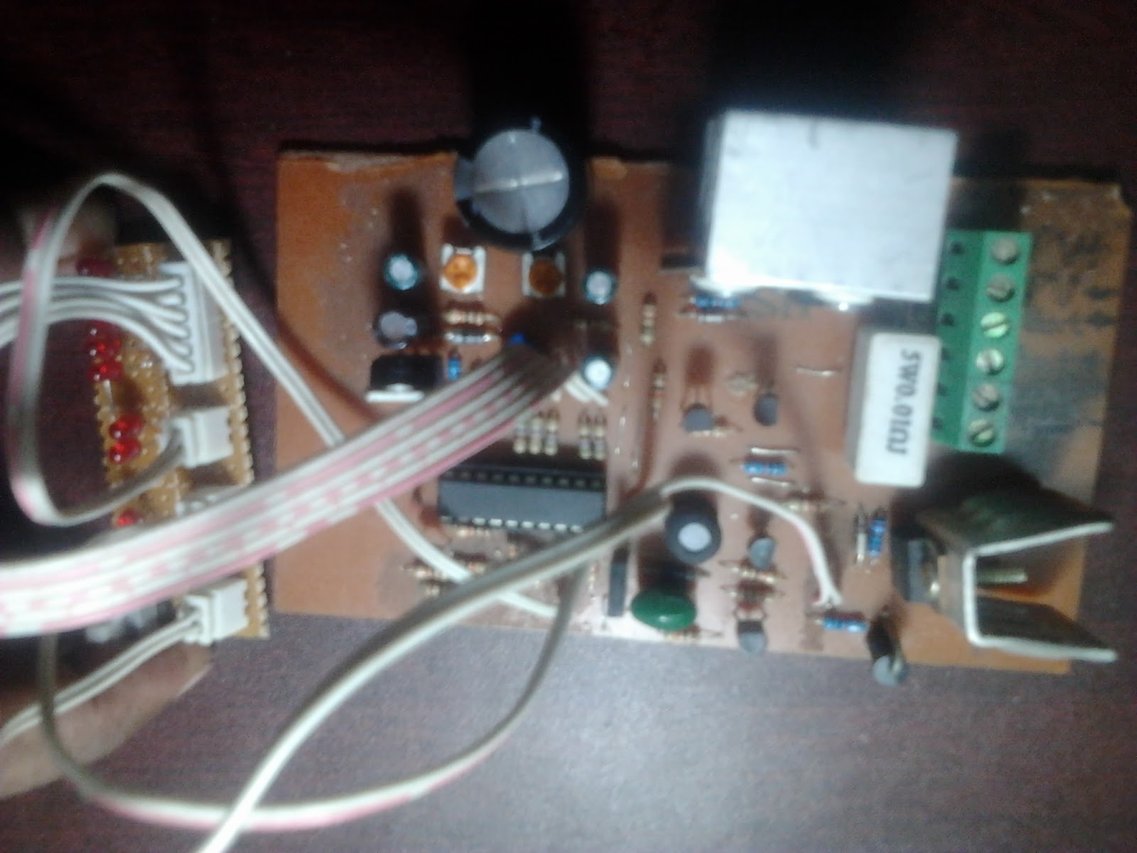
While working at Nice Electrical and Electronics Industries Limited as part-time researcher and circuit developer, I have designed Solar Charge Controllers of different capacity (15A to 50A).
The charge controller is controlled by a 16F690 PIC microcontroller. The microcontroller first senses the input voltage from the solar panel. If the voltage is above 12.6V and below 19V, charging takes place.
Circuits 1, 2 and 3 share similar hardware but the control methodology is different.
The MOSFET is configured as a high-side switch. A charge-pump circuit is set up that boosts the input voltage to a voltage between 24V and 36V (depending on input voltage). The microcontroller provides the PWM signal to the boost stage. The boosted voltage (between 24V and 36V) is used to drive the high-side MOSFET.
Circuit 1 is simple on/off type series pass charge controller. When voltage is between 12.6V and below 19V, the microcontroller turns on the MOSFET and the voltage from the panel is provided to the battery via the MOSFET. The battery voltage is monitored and when the voltage is above 14V, the charging is stopped until voltage falls below 13.7V.
Circuit 2 is PWM based. The microcontroller generates the PWM signal depending on input voltage. The MOSFET is driven based on the PWM signal and the battery is charged. When the battery reaches 14V, charging is not stopped. Instead, duty cycle of PWM is reduced. This acts like "trickle" charging, to keep the battery fully charged.
Circuit 3 is MPPT (Maximum Power Point Tracking) based. The microcontroller generates the PWM signal and drives the MOSFET accordingly, while adjusting duty cycle to "search" for the maximum power point to maximize charging current. The circuit currently works and charges the battery although the maximum power point tracking isn't great. I am going to have to further work on this circuit to make it perfect.
_________________________________________________________________________________________________________________________
300W 12VDC to 220VAC SMPS-based Solar Inverter


Circuit 1
Circuit 2
While working at Nice Electrical and Electronics Industries Limited as part-time researcher and circuit developer, I also designed Solar Inverters of different capacity.
Circuits 1 and 2 are both DC-AC converters. 12V DC is first stepped up to 240VDC using a push-pull converter. SG3525 generates the PWM signal. The high voltage DC is kept regulated.
In Circuit 1, a 50Hz auxiliary transformer is used for output voltage sensing and the voltage output from the 50Hz auxiliary transformer is fed to the SG3525 which uses it to keep the output voltage constant.
In Circuit 2, a voltage feedback loop is designed using TL431 and opto-coupler, eliminating the need for a 50Hz auxiliary transformer.
The high voltage DC is then converted to AC by a full-bridge stage using 4 MOSFETs. The 50Hz signals are generated by the 16F690 microcontroller. The signals are fed into high-low side MOSFET drivers L6385E using opto-couplers so that the low-voltage side (where the microcontroller is) is isolated from the high-voltage side (where the drivers and MOSFETs are). The drivers drive the MOSFETs according to the signals generated by the microcontroller. The output voltage is kept constant as the high-voltage DC bus is regulated by the SG3525.
The microcontroller also senses the battery voltage and shuts off the inverter when battery voltage falls below 10.8V, providing low-voltage protection. The load current is also sensed by the microcontroller to provide over-load protection.
All MOSFETs are mounted on heatsinks for heat dissipation. The transformer, using ETD39 core, was wound by me as tailor-made wound ferrite transformers are not available in Bangladesh.
The entire circuit from concept to design to implementation was done by me as nothing ready-made is available here!


Dear Tahmid,
ReplyDeletePlease post the complete schematic with source code of your solar charge controllers if it possible. Thanks
hi tahmid,
ReplyDeletei have a dought did the ferrite transformer step up the 12vdc to 230vdc?with out any frequency?
The transformer stepped up 12V to 250V high frequency AC. High frequency (40kHz) was used.
ReplyDeleteThis was then rectified using an ultrafast recovery bridge rectifier (made with 4X ultrafast rectifier diodes) and then filtered with LC filter to provide clean DC output, which was then converted to AC using a full-bridge.
HELLO TAHMID with out voltage regulator how you can charge the battery ? what i mean is a 12v solar panel output is 18v like that but the battery needs nearly 14.5v to charge .with out a proper regulator how you can regulate 50A such a high currents?
ReplyDeleteThe microcontroller drives a MOSFET. The configuration acts like a buck converter when voltage is too high. When voltage is near battery level, no regulation is provided. So, when output is too high, the microcontroller + MOSFET combination is the regulator itself. The advantage to using this configuration is that it can be used both as a voltage regulator and as a current regulator.
ReplyDeletethat s good can you upload the circuit of buck converter to regulate voltage 19v to 14?
ReplyDeletehi thamid can i drive the mosfet with pwm ic ?
ReplyDeleteHi,
ReplyDeleteIf you're using PWM and the IC has drivers built-in, then of course you can drive the MOSFET(s) with the IC. However, keep in mind the required topology and control methodology. If the circuit requires low-side MOSFET drive, you can check here: http://tahmidmc.blogspot.com/2012/12/low-side-mosfet-drive-circuits-and_23.html
thamid i am asking about solar charge controller ,can i drive the mosfet with pwm output .such a way that the voltage from pannel charge the battery when the mosfet gate get signal from pwm ?
ReplyDeleteOf course you can. Just keep in mind the necessary control methodology and drive technique/topology.
ReplyDeletethanku thamid what is the sutable frequency to drive it?
ReplyDeleteThat depends on you. The higher the frequency, the smaller the required inductances and capacitances, but the higher the switching losses and the greater the drive complexity.
ReplyDeletehi thamid can i drive with ka3525 by connecting pins 11 and 14 both to a same mosfet gate ..i mean mosfet signal will be drived http://tahmidmc.blogspot.in/2012/12/low-side-mosfet-drive-circuits-and_23.html as shown in your articel like this..can i connect pin 11 and 14 to drive the same mosfet ?
ReplyDeleteDear Tahmid,
ReplyDeletePlease send the complete schematic with source code of your solar charge controllers & inverter if it possible.
Thanks
pradip
email - kolaypradip@yahoo.co.in
hi thamid i want to drive the 60amp rated mosfet with pwm,the mosfet switches buck converter,if the frequency is 20khz then what will be required inductance value?
ReplyDeleteYou can find the required formulae in books such as Marty Brown's "Power Supply Cookbook". You can also use online tools such as http://schmidt-walter.eit.h-da.de/smps_e/abw_smps_e.html
ReplyDeleteAs for driving MOSFETs from SG3525, you can do it directly usually. But when the MOSFET has high gate capacitance and needs to be switched quickly with high current, use a gate driver, using discrete parts or a dedictaed driver.
hi thamid ,i will say calculation plz say wether it was correct or worng
ReplyDeleteassume:
vin=19v,vout=14,D=vin/vout,iload=30amp,frequency=50khz,i ripple =0.3*(i load)
inductor=(vin-vout)*(D/frequency)/i ripple
inductor =15.07 micro henry
L = (Vinmax - Vout) * (D / f) * (1/ dI)
ReplyDeleteD = Vout / Vinmax
dI = LIR * Ioutmax
So,
D = 14 / 19
dI = 0.3 * 30 = 9
L = [ (19-14)*(14/(19*50000))*(1/9) ] H
L = 8.2 uH
This is the minimum inductance. So, the actual inductance should be higher.
hi thamid ....if the current in was 30 amp ..then what will be the current out for this above specification buck converter?
Deletethanku thamid
ReplyDeletehi thamid can i drive gate directly from the microcontroller inorder to flow pannel voltage to battery through battery?or did it require any frequency to drive mosfet gate?
ReplyDeleteFor just on/off control, you can just drive the MOSFET on. For PWM or MPPT, you need pulsed drive.
DeleteRegards,
Tahmid.
Hi thaid
ReplyDeleteCan explain simple working of MPPT Charger ,and its advantages?
sandy,
ReplyDeleteIt depends on control scheme. For linear pass controllers, no drive frequency is required. For PWM/MPPT the signal is pulse width modulated.
Make sure that you use a gate driver.
ismailpp2008,
It will be difficult to explain it all. You will get better results if you search Google for "how does mppt charge controller work".
Hi Tahmid,
ReplyDeletecan you please help me modify this circuit
http://vkelektroniks.blogspot.in/2012/09/microcontroller-based-solar-charger.html
i want to use a 40 amp battery and 100 watt solar panel
thank you
Hi Tahmid,
ReplyDeletein this circuit http://new.electronicsforu.com/newelectronics/circuitarchives/view_article.asp?sno=823&title=&id=664&article_type=1
what is vr1 and vr2 for? and how can i calibrate this circuit
thank you
Hi,
ReplyDeleteFor the circuit here:
http://vkelektroniks.blogspot.in/2012/09/microcontroller-based-solar-charger.html
Use a relay with higher current rating. Increase capacity of D1 and use values of T3 and F1 as required.
halo Tamid,
ReplyDeletefor a 12 volt, 17ah battery, usually what is maximum charging current?
cant find the datasheet.
Hi,
Delete10% of the battery capacity is ideal for maximum battery life. However can charge upto 20% of battery capacity because we have limited time available from solar system.
The higher the charging current, the lower the charge time.
ReplyDeleteFor long battery life, charge at C/10. So, in this case, it would be 1.7A for the 17Ah battery.
halo Tahmid,
ReplyDeletethank you. sorry for misspelled your name.
for long battery life, 1.7A is good but 10 hours of charging is time consuming.
So i am planning to shorten the charging time.
Because sun is not always in max irradiance all the time.
Any recommend charging current in the trade off of lower battery life?
You can increase charging current. As long as you don't overcharge the battery, there shouldn't be a problem. Reduce charging current drastically before the battery voltage reaches, for example, 13V. Then, there shouldn't be too much of a problem. Battery life may be slightly reduced, but not too much.
ReplyDeleteThank you Tahmid.
ReplyDeleteThanks for ur reply
ReplyDeletein the circuit http://vkelektroniks.blogspot.in/2012/09/microcontroller-based-solar-charger.html
can u please tell me which components can i use for f1 and t3 for 40 amp battery
thank u
It depends on the load you are going to take. For loads of less than 10A, the components shown are okay.
ReplyDeletehi thamid
ReplyDeletei want to make solar charger , But which is the best and Cheapest Methode to find dc Current
Hall effect : which is the cheapest [for 30A max ,20mv/A resolution,]
Can i use Shunt resistor method : like using 5cm length 1mm radius Copper [0.0002ohm] and LM324 op-amp for amplify this uV . please give good solution and tell me is any problem for opamp type sensing [above diccussed].
Hi,
ReplyDeleteYou can use shunt but you might want to increase the resistance. 0.0002 ohms is too low and will introduce a lot of error.
Hall effect sensor will be better but MUCH more expensive.
Regards,
Tahmid.
Hi,
ReplyDeleteI am having 850va inverter ,which gives 220volts output.
on ups mode my fans are becoming slow.
how to increase output voltage?
Regards
rajesh
You need to adjust the feedback in the circuit to slightly increase the voltage. This can usually be done simply by rotating a variable resistor (pot) in the correct way.
DeleteIncrease the voltage to 230VAC and this usually works! Don't increase beyond 230V though - you might damage your fans if the voltage is too high!
Regards,
Tahmid.
Dear Tahmid,
ReplyDeletePlease send the complete schematic with source code of your solar charge controllers & inverter if it possible.
Thanks
uzeyirilden@hotmail.com
You can get one here (not mine): http://archive.siliconchip.com.au/cms/A_112794/article.html
Deletehey tahmid can u tell me how much it costs for MPPT charge controller
ReplyDeleteIt depends on your choice of components selection - the microcontroller you choose, the switching components, drivers, etc. It costs more than linear type on/off controllers, but not too much more if you just want simple MPPT charge controlling without much other "advanced" features.
DeleteRegards,
Tahmid.
sir i need a mppt charger conroller circuit for 100w
ReplyDeletehttp://archive.siliconchip.com.au/cms/A_112794/article.html
Deletecan you please send me complete circuit and source code of any charge controller plz
ReplyDeletesunilraheja24@yahoo.in
thank you
http://archive.siliconchip.com.au/cms/A_112794/article.html
Deletehi thamid ..is buck converter will give more output current than input current?
ReplyDeleteTypically, a buck converter, compared to the input, reduces the output voltage and increases output current.
DeleteRegards,
Tahmid.
I enjoy the stuff you put in here. Very pertinent information. Consider yourself book-marked. solar inverters manufacturers in bangalore
ReplyDeleteHi Tahmid,
ReplyDeleteI am new in your blog.
I want to make a MPPT based Charge controller plz help me to make this project.
Please send me basic concept on my mail id.
missmehta1988@gmail.com
A simple Google search returns a lot of useful results.
DeleteHere's one you can use to get started: http://en.wikipedia.org/wiki/Maximum_power_point_tracking
Regards,
Tahmid.
Hi Tahmid,
DeletePlease send me schematic diagram of MPPT based charge controller circuit.
i am designing the circuit for solar charge controller using PIC16f676 ,
ReplyDeletemy logic is clear but i doubt the initialization process is wrong thats why i am not getting the desired result .
my input output pin are not working as per my requirment , can you provide your email id so that i can send you the file and you can check it there
hi
ReplyDeletekindly send me all details if possible
adityapurwar007@gmail.com
Hey Tahmid ,
ReplyDeleteI am getting very low value of current ( in micro amp) after the mosfet. Please tell me how to improve it.
And its really difficult for me to design ferrite based transformer tell me how to proceed .
towardsonedirection@gmail.com
its my humble request to all of you please give me appropriate path.
Thanks- Gizem
Hi Tahmid,
ReplyDeleteI am posting this request assuming you will be able to help me solving my problem. I have designed Solar charge controller using 555 as a comparator that drives 4xMOSFET (IRF4321) in parallel. The circuit is meant for charging 48V batteries with max charging of 30-40 Amps. The circuit works well in most of installations. However in the situation where the batteries are faulty or bad or deeply worn, i am experiencing many cases of MOSFET burned or shorted. So my questions are:
1. What could be the reason of MOSFET going faulty, shorted due to battery fault. My circuit is just comparing the battery voltage to turn on or off the MOSFET. It doesnot monitor other parameters like battery temperature, batttery type (Flooded, AGM, VRLA). FYI my switching circuit is ON/OFF type not PWM.
2. In case the MOSFET is shorted then all the power generated by solar goes to battery as there is nothing to control by control circuit. The result in such case is that battery is overcharged and damaged too. Is there any way to avoid this situation such that battery charging is stopped if MOSFET gets shorted?
Looking forward for your valuable suggestion please.
Regards,
Deepak
Hi Tahmid,
ReplyDeleteI was looking for your advice in solving a very common problem i am facing solar charge controller circuit. I have designed and installed 48V, 30Amp On/Off based solar in many live sites for telecoms. The circuit worked well for most of the installation but in certain instances i am facing problem of MOSFET getting shorted (Drain and Source) which i have not been able to identify the reason.
I understand that MOSFET becoming shorted while switching such large current is quite common because i have seen similar MOSFET shorting problem in good controllers like "Morningstar". The biggest problem in my design is that in case MOSFET Drain and source get shorted then it becomes like direct connection from Solar to Battery resulting battery overcharge further causing damage to battery. Is there any way i can enhance my circuit to avoid this situation.
I have been looking for answer to this issue for years and have posted my request in many blog but i have not found a concrete answer from any one so far. In fact this is my second request in this blog too. Will you be able to help me?
Deepak
Nice one tahmid you are doing well
ReplyDelete