
PIC32 Development: Proto board on verroboard

My PIC32 protoboard in action - Measuring the speed of the internal ADC and displaying it on the 7 Segment Display board
It’s been a while since I last posted. My second semester at
Cornell has begun and it has been busy.
My first semester ended mid December
2013. So I went back home to Dhaka, Bangladesh for winter break.
Unfortunately, due to the ongoing political crisis in
Bangladesh at the time, I could not spend too much time outside home. Thus I ended
up spending a lot of time on electronics. There were two aspects to this over
my winter break. One, I spent a lot of time with the PIC32, writing some code,
doing tests with the peripherals and making a “proto board”. That, I must admit,
was a lot of fun. It was a continuation of my independent study (see: http://tahmidmc.blogspot.com/2013/09/200000-views-ithaca-arm-and-dmips.html
and http://www.tahmidmc.blogspot.com/2014/01/a-comparative-study-between-at91sam3x8e.html).
The second part was me developing an AC-AC voltage stabilizer (more on that
later, in another article) and also toying around with the Arduino Due (also
part of my independent study).
I had previously used the Microstick II from Microchip for
experimenting with the PIC32. However, I felt a need to use a more “robust”
board for prototyping (don’t get me wrong; I’m not bashing the Microstick II –
it’s a neat little board). So, I decided to make one myself. I used a
verroboard and just put on the microcontroller and also the required basic
connections. For the microcontroller, I used the PIC32MX250F128B which comes in
a nice user-friendly PDIP28 package. This is the same microcontroller on the
Microstick II and is the same microcontroller I had been working on.
The basic layout of the board is:
- There is an on-board 3.3V regulator for powering the PIC32. I chose against using an LDO voltage regulator since I did not have in hand any LDO regulator that can accept reasonably high voltages (by that I mean about 12-16V). I wanted to use an external 12V or 15V power supply for powering the board, so that I could use that same supply voltage for other stuff running at the same time. Thus I used the TI ua78M33C voltage regulator that I had with me (I had gotten them off of Mouser a while before going home).
- Decoupling capacitors on the power lines.
- A 10uF “filter capacitor” necessary for the microcontroller. This capacitor is placed between the VCAP and VSS pins on the microcontroller. The crucial part here is that, the capacitor must have relatively low ESR (equivalent series resistance), defined by Microchip as <1Ω. I had to go through my collection of capacitors and manually measure the capacitors’ ESR using the ESR meter.
- A push-button for enabling/disabling the PIC32. When pushed/closed, the PIC is disabled (MCLR – master clear – is held low). When the switch is open, the PIC is enabled (MCLR is pulled up by a pull-up resistor).
- Connectors for taking connections/wires out of the board onto a breadboard or other board. The connectors are connected so that every single pin of the microcontroller is connected to one connector pin/line.
- ICSP (in-circuit serial programming) header to allow in-circuit programming of the PIC32 using a Microchip PICKIT3 programmer/debugger.
- An LED connected to RA0 (pin 2) of the PIC32. This LED is used as a “debug LED” – just as an indicator of sorts that is already connected on the board for use. LEDs are always used in circuits after all. I chose to use RA0 for connecting the LED since this was the same pin to which the LED was connected to on the Microstick II board.
- A variable resistor. This is used to provide a varying analog voltage (from 0V to 3.3V) to the PIC32 RB15 (AN9 – pin 26). This was put on the board so that I could have an analog voltage for testing if/when I needed it. However, since this won’t be necessary in every circuit and I might want to use RB15 for something else, I put in a latching push switch which when pushed/closed will connect the analog voltage (the wiper of the variable resistor) to RB15 of the PIC. When the switch is open the wiper of the variable resistor is NOT connected to RB15, freeing that pin up for other use.
That’s about it as far as the PIC32MX250F128B “proto board”
goes. There’s another board that I made on verroboard for testing – that’s the 3
digit 7 segment display board. This board consists of – you guessed it – a 3
digit 7 segment display. But the key thing is that it has driver transistors on
the board so that I don’t have to worry about drive current from the
microcontroller. There are 7 seven driver transistors BC547 working in the
common collector (emitter follower) mode to just act as an analog buffer and a
current amplifier. The display itself consists of 3 common cathode “digits”.
So, for each of the digit common cathodes, there is a driver transistor – I have
used the 2SD882 transistors. In all honesty, such a high capacity transistor is
not needed; but I did not have any BC337/PN2222A transistors in hand and this
was the only non-power transistor I had that was capable of withstanding more
than 100mA current.
I’ve done quite a few projects with these boards. I’ll be
posting these from time to time. For now, here are some pictures.
Here’s a picture of the two boards along with some wiring
between them and some additional components on a breadboard.

Here’s one with the 7 segment display in action:
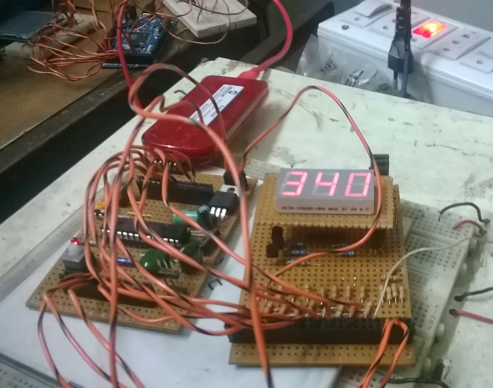
You can see the PICKIT3 connected as well.
Here’s a view of just the PIC32 protoboard:


hi may i get schematics and parts list
ReplyDeletethank you