Embedded Systems and Power Electronics

Total Pageviews

About Me

My photo
I am currently a PhD student at UC Berkeley, following a 6-year journey working at Apple after my undergrad years at Cornell University. I grew up in Dhaka, Bangladesh where my interest in electronics was cultivated, resulting in the creation of this blog.

BTemplates.com

Powered by Blogger.

Sep 30, 2012

For the love of football (soccer)


Our School Team With The Championship Trophy


My number 13 is not unlucky for me


The Interschool Champion Team


Yesterday (29th September 2012), our school team became champion of the Interschool Football (Soccer) Tournament, beating Aga Khan School in the final. I am one of the proud members of our team and am very happy having won our school the first Senior Championship in four years. But, behind this happiness, there is bitterness, sorrow and dissatisfaction.

Our school has three football fields. However, the authority does not want us to play too much and does not allow us to play much. There are not many school tournaments to play in either. The school authority wants us to indulge our efforts in studies only and does not want us to play much. So, there is not much practice in school.

The sector in which my house is located, has become, like most of Dhaka, a concrete jungle. There is not a single playground in the entire sector. So, to play or practice properly, I had to go to a different sector, almost three miles away, where there is a field. However, during the day - from morning to evening, the ground is occupied by players from that sector or nearby areas.

So, I chalked out a plan. On Fridays, Saturdays and on other holidays, I, along with my friends from our sector and nearby areas, go to the ground very early in the morning (while it is still dark) and start practicing and playing to our hearts' content until at around 9 in the morning, players from that sector come and occupy the field.

Occasionally, my friends and I would play on the streets, just passing the ball around and playing the odd match of street football.

I organized a non-professional team Chapati FC, where my friends and I would play. I organized friendly matches and we played against other non-professional teams and sometimes participated in non-professional football tournaments.

Like me, the other players in our school team, practiced football outside of school, improving and building themselves with their own initiatives on their own merit, and brought our school fame.

Despite all these difficulties and limitations, we love football. I pray and hope that one day our school authority will realize that football and other sports are not less important than academics.

A bookworm, no matter how brilliant he is, may not always be as helpful to society as a healthy and fighting fit meritorious student can be. After all, the phrase goes "Survival of the fittest...."

Sep 28, 2012

Failure is the pillar of success


Some of the unsuccessful circuits in the early stage of SMPS learning

During the last five years of my venture in SMPS circuits, I had failed many hundred times trying to design successful SMPS circuits. Since I am not institutionally trained, most of my circuits were based on test and trial, taking help from books, internet, forums, application notes, datasheets, etc. Hundreds of hours of failure could not deter me from relentless pursuit to learn - rather, taking lessons from these failures, I moved forward. Now, I am somewhat confident that I learnt a little bit of SMPS and can venture in SMPS circuits confidently.

Some of my SMPS circuits


Here are a few of the SMPS circuits I made, employing flyback, push-pull, half-bridge and full-bridge topologies.

_________________________________________________________________________________________________________________________


 Test 
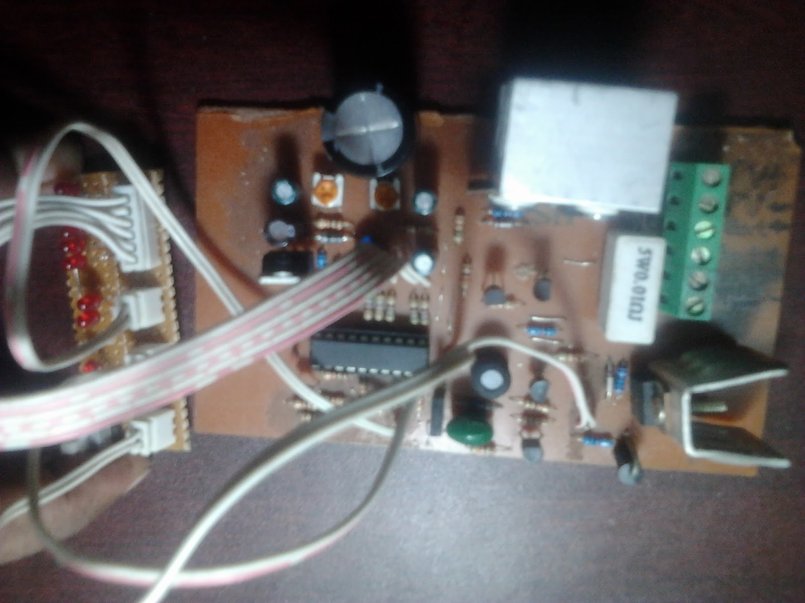
setup on verroboard of half-bridge SMPS circuit with SG3525 and IR2110 for battery charging. See description below. This is the verroboard prototype of the circuit built on PCB below.
_________________________________________________________________________________________________________________________


Offline Half-bridge converter
Input: 160 to 240V AC 50/60Hz
Output: 14.5v 10A (max)
Final test circuit (on PCB) for battery charging. Successful. To be incorporated in SMPS inverter with charger.

The primary side PWM is controlled by SG3525 PWM chip. Frequency of operation is around 50kHz. The output signals of the SG3525 are fed into a IR2110 high-low side driver which drives the 2 MOSFETs (IRF840) configured for half-bridge topology. ETD39 core is used for the transformer. It was wound by hand at home by me. A primary side snubber is used. 2 bulk capacitors (470uF, 200V each) are used for the half-bridge converter.

An auxiliary 50Hz transformer (18V 100mA) is used to provide auxiliary low voltage output, which is rectified, filtered and regulated to 12V with a 7812 to power the SG3525, IR2110 and related circuitry. Since average current is low, voltage difference between 7812 input and output is not too great, the power dissipated by the 7812 is not too high and no heat sink is required.

The output of the ETD39-based transformer is rectified with schottky rectifier STPS3045 and an LC filter is used to filter to pure DC. The output voltage is kept regulated using a zener-optocoupler based voltage feedback loop. The STPS3045 is mounted on a heatsink. The output inductor is the large toroidal inductor beside the 50Hz transformer. It has not been mounted on the PCB.

NTC has been used at the input side to limit inrush current due to charging of the LARGE BULK capacitors at the primary side. A fuse has been used for protection in case of short-circuit.

A 200-ohm resistance is used at the output as "dummy load".

I have designed the PCB myself and have wound the transformer myself, at home.

_________________________________________________________________________________________________________________________


1A offline flyback power supply with UC3842
Input: 160 to 240V AC 50/60Hz
Output: 14.5v 1A (max)
Could be used as auxiliary power supply.

The primary side PWM is controlled by UC3842 chip. The UC3842 drives the high voltage MOSFET (IRF840) directly as it has a built-in MOSFET driver. 50k resistor is used for startup from the high voltage DC bus - the UC3842 has built-in zener diode that limits voltage, provided current is low enough.

EE25 core was used for the transformer. I wound the transformer myself.

The output of the transformer is rectified with ultrafast rectifier 31DF6 and capacitor is used to filter to pure DC. The output voltage is kept regulated using a zener-optocoupler based voltage feedback loop.

NTC has been used at the input side to limit inrush current due to charging of the capacitor at the primary side. A fuse has been used for protection in case of short-circuit.

This is one of the oldest SMPS circuits I had made. I made it sometime in 2008.

_________________________________________________________________________________________________________________________


2A flyback power supply with TOP-GX
Input: 160 to 240V AC 50/60Hz
Output: 14.5v 2A (max)

The power supply is based on the dedicated offline-switcher "TOPSwitch-GX" TOP245Y, which contains both the primary PWM controller and the high-voltage MOSFET.

EE25 core was used for the transformer. I wound the transformer myself.

The output of the transformer is rectified with ultrafast rectifier MUR420 and LC filter is used to filter to pure DC. The output voltage is kept regulated using a TL431-optocoupler based voltage feedback loop.

NTC has been used at the input side to limit inrush current due to charging of the capacitor at the primary side. A fuse has been used for protection in case of short-circuit.

This is one of the oldest SMPS circuits I had made. I made it sometime in 2008.


_________________________________________________________________________________________________________________________


 12VDC to 280VDC DC-DC converter for CFL inverter
Input: 11VDC to 14VDC
Output: 280VDC 60W
Was designed to drive four 15W CFL's from 12V battery.

The primary side PWM is controlled by SG3525 PWM chip. Frequency of operation is around 70kHz. The SG3525 drives the 2 MOSFETs (IRF3205) configured for push-pull topology. EI33 core is used for the transformer. It was wound by hand at home by me. The 2 MOSFETs are mounted on heatsinks.

The output of the transformer is rectified to DC with 4 ultrafast diodes (UF4007) configured as a bridge rectifier. LC filter is used to convert output to pure DC.

_________________________________________________________________________________________________________________________


 Flyback circuit using TOP-GX

Input: 160 to 240V AC 50/60Hz
Output: 12V 3A (max)

The power supply is based on the dedicated offline-switcher "TOPSwitch-GX" TOP245Y, which contains both the primary PWM controller and the high-voltage MOSFET. ETD34 core was used for the transformer. I wound the transformer myself.
_________________________________________________________________________________________________________________________


12VDC to 220VAC Inverter (200 to 300W) using SG3525, IR2113 and PIC16F676 with features such as low-battery and overload protection
The primary side PWM is controlled by SG3525 PWM chip. It drives 2 MOSFETs (IRF3205) in push-pull configuration. The MOSFETs drive the transformer. ETD34 core was used for the transformer. The output of the transformer is converted to DC. The high-voltage DC is kept regulated by the SG3525 using direct resistive voltage-divider based feedback. This high-voltage DC is then converted to 50Hz AC using 4 MOSFETs (IRF840) in full-bridge configuration. The quasi-sine signal is generated by the 16F676. The output signals are fed into 2 IR2113 high-low side drivers that drive the MOSFET full-bridge. The 16F676 also monitors the battery voltage for low-voltage cut-out. It also monitors the load current for overload protection.

I made this circuit sometime in 2010 after lots of failure in design and implementation.

Research and Design of Solar Products


                                  SOLAR CHARGE CONTROLLERS


Circuit 1  - On/Off                                                                                  
Circuit 2 - PWM


Circuit 3 - MPPT
 
While working at Nice Electrical and Electronics Industries Limited as part-time researcher and circuit developer, I have designed Solar Charge Controllers of different capacity (15A to 50A).

The charge controller is controlled by a 16F690 PIC microcontroller. The microcontroller first senses the input voltage from the solar panel. If the voltage is above 12.6V and below 19V, charging takes place.

Circuits 1, 2 and 3 share similar hardware but the control methodology is different.

The MOSFET is configured as a high-side switch. A charge-pump circuit is set up that boosts the input voltage to a voltage between 24V and 36V (depending on input voltage). The microcontroller provides the PWM signal to the boost stage. The boosted voltage (between 24V and 36V) is used to drive the high-side MOSFET.

Circuit 1 is simple on/off type series pass charge controller. When voltage is between 12.6V and below 19V, the microcontroller turns on the MOSFET and the voltage from the panel is provided to the battery via the MOSFET. The battery voltage is monitored and when the voltage is above 14V, the charging is stopped until voltage falls below 13.7V.

Circuit 2 is PWM based. The microcontroller generates the PWM signal depending on input voltage. The MOSFET is driven based on the PWM signal and the battery is charged. When the battery reaches 14V, charging is not stopped. Instead, duty cycle of PWM is reduced. This acts like "trickle" charging, to keep the battery fully charged.

Circuit 3 is MPPT (Maximum Power Point Tracking) based. The microcontroller generates the PWM signal and drives the MOSFET accordingly, while adjusting duty cycle to "search" for the maximum power point to maximize charging current. The circuit currently works and charges the battery although the maximum power point tracking isn't great. I am going to have to further work on this circuit to make it perfect.

_________________________________________________________________________________________________________________________


                        300W 12VDC to 220VAC SMPS-based Solar Inverter


Circuit 1
Circuit 2                         


While working at Nice Electrical and Electronics Industries Limited as part-time researcher and circuit developer, I also designed Solar Inverters of different capacity.

Circuits 1 and 2 are both DC-AC converters. 12V DC is first stepped up to 240VDC using a push-pull converter. SG3525 generates the PWM signal. The high voltage DC is kept regulated.

In Circuit 1, a 50Hz auxiliary transformer is used for output voltage sensing and the voltage output from the 50Hz auxiliary transformer is fed to the SG3525 which uses it to keep the output voltage constant.

In Circuit 2, a voltage feedback loop is designed using TL431 and opto-coupler, eliminating the need for a 50Hz auxiliary transformer.

The high voltage DC is then converted to AC by a full-bridge stage using 4 MOSFETs. The 50Hz signals are generated by the 16F690 microcontroller. The signals are fed into high-low side MOSFET drivers L6385E using opto-couplers so that the low-voltage side (where the microcontroller is) is isolated from the high-voltage side (where the drivers and MOSFETs are). The drivers drive the MOSFETs according to the signals generated by the microcontroller. The output voltage is kept constant as the high-voltage DC bus is regulated by the SG3525.

The microcontroller also senses the battery voltage and shuts off the inverter when battery voltage falls below 10.8V, providing low-voltage protection. The load current is also sensed by the microcontroller to provide over-load protection.

All MOSFETs are mounted on heatsinks for heat dissipation. The transformer, using ETD39 core, was wound by me as tailor-made wound ferrite transformers are not available in Bangladesh.

The entire circuit from concept to design to implementation was done by me as nothing ready-made is available here!

Circuits made from necessity


LCR METER with PIC16F88


 In SMPS circuits, it is necessary to know the inductance of the inductors and transformer windings. However, it is not possible to know the inductance without the use of a meter for measuring inductance (eg LCR meter). In earlier stage of my venture in SMPS circuit design, I could not procure an LCR meter for use. So, I made one using 16F88 PIC microcontroller for my own use, taking help from internet. It has been made sometime in 2008. I still use it.

______________________________________________________________________________________________________________________________

PICKIT2 Clone

 
Circuit 1

 Circuit 2                      


When I was in class six, my father introduced me to PIC microcontrollers and gave me a programmer. After one year, the programmer got damaged. I failed to procure a new one as programmers available here were expensive universal ones - programmers for PIC only were not available. So, I made programmers for myself, taking help from internet and this PICKIT2 clone is my latest one - made sometime in 2010. Circuit 1 is the prototype constructed first on verroboard and Circuit 2 is the one I made on PCB after modifying existing designs collected from internet. I am still using Circuit 2 for programming all 8-bit and 16-bit PIC microcontrollers for my use.
______________________________________________________________________________________________________________________________
REMOTE CONTROLLER FOR 2 LIGHTs and 1 FAN


My mother complained that for morning prayer, getting up from bed and switching on the light becomes difficult for her and hence, she asked me whether I could make a remote controller to switch on lights without getting up from bed, which she saw in her sister's house (Chinese made). So, I made one to turn two lights on/off and to turn on/off and control speed of one fan using the existing remote of our Sony TV. Later on, I found that it has good commercial value as well.

It is made using a 12F675 PIC microcontroller. The microcontroller is powered off a non-isolated resistor-capacitor based auxiliary power supply. The microcontroller decodes the signal it receives from the IR sensor (PNA4602). The signal is given from the Sony TV remote. The protocol used by the remote is SIRC, so the microcontroller decodes the received signal according to the SIRC protocol. The microcontroller then turns on/off triacs for switching on/off, as well as using pulse skipping modulation for controlling speed of the fan. I made the code using mikroC compiler.


The SIRC protocol used in my remote controller:

The SIRC protocol uses a pulse width encoding of the bits. The pulse representing a logical "1" is a 1.2ms long burst of the 40kHz carrier, while the burst width for a logical "0" is 0.6ms long. All bursts are seperated by a 0.6ms long space period. The recommended carrier duty-cycle is 1/4 or 1/3.